

Welcome to my world of Sn3 Scale Model Railroading

Timberline Lead & Zinc Mine
By
Tom Troughton, MMR
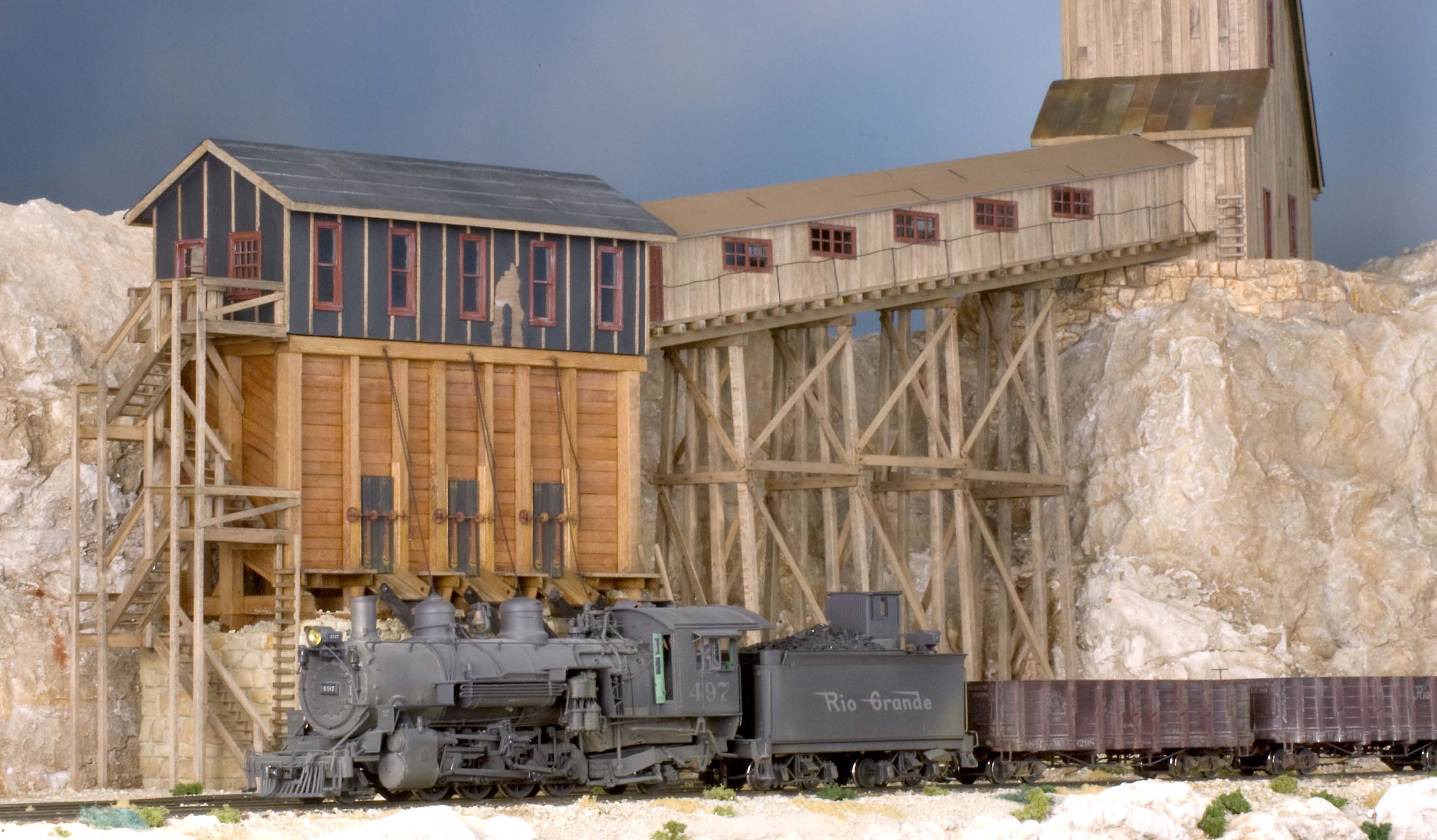 This document features the Timberline Mine #1, the largest mining complex operated by the Cimarron Lead and Zinc Company, that's located on the upper level of my Sn3 Cimarron and Tall Timbers Railroad. Construction of the scratch built mining complex was covered in two installments that appeared in the February and March 2013 issues of Railroad Model Craftsman magazine. While some of the more than 200 images used in this document were submitted and used in the printed versions, I wanted to include them here to better document the step by step process used to construct the mining scene. Rather than providing volumes of text, I also decided to just use the photo captions to explain how things were completed. If you wish to read the more detailed process, check out the RMC articles. I hope you enjoy seeing how the mining complex was built. | |
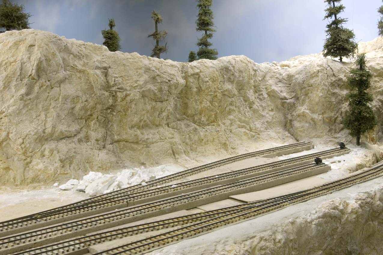 Photo 1 This is the area where the new ore bin, conveyer building and mine will be located. Rock demolition work has already begun to make room for the new structures. This area originally was to be used as a timber yarding operation, but the log cars and three truck shay were sold and mining interests took over. | 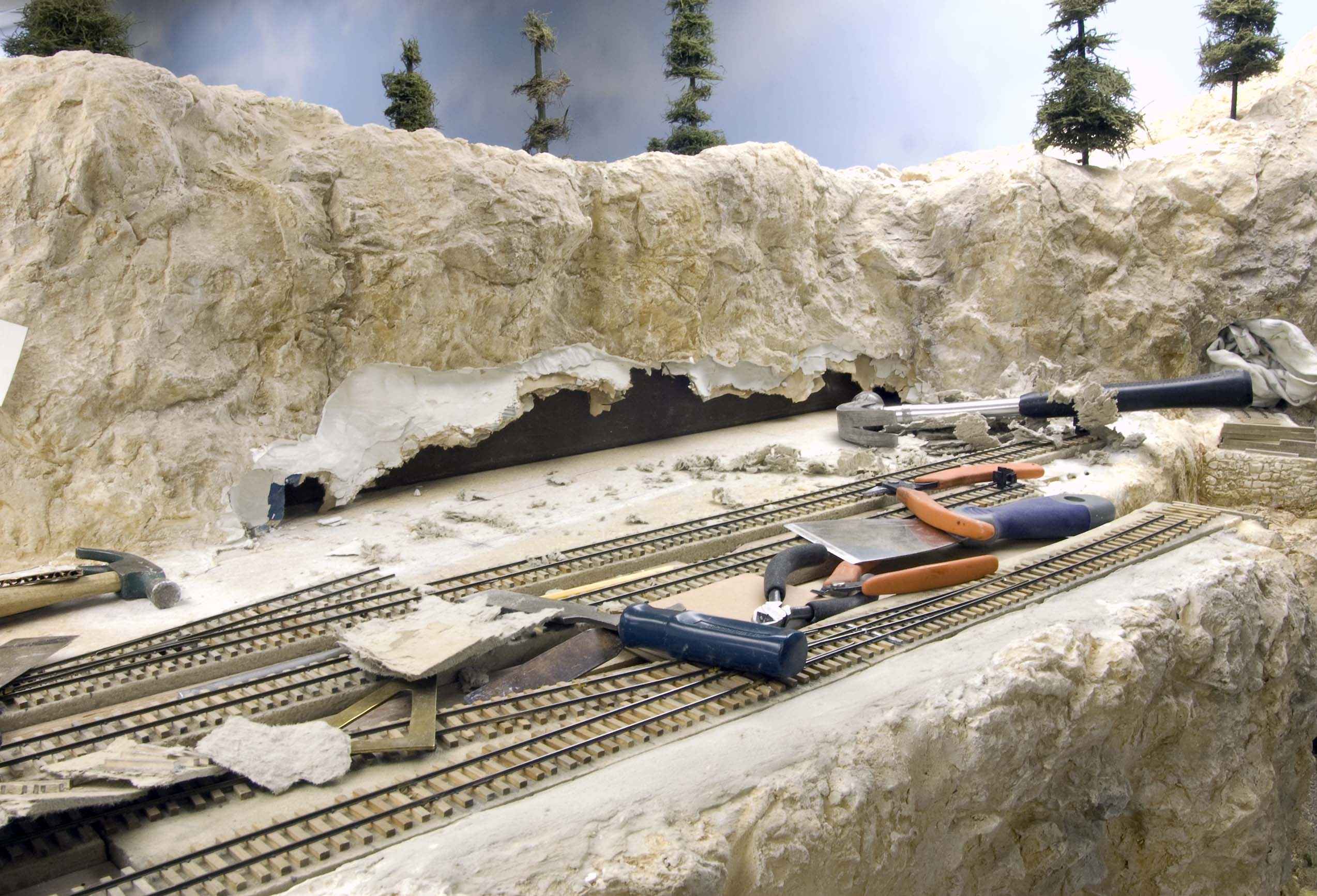 Photo 2 It wasn’t a pretty sight for a while, as almost every tool in my tool box was used to remove the excess plaster to make room for the ore bin. One of the spur tracks planned for the logging scene has already been removed in this view. To prevent damage to a timber trestle that was located near the black handle of the hammer, it was also relocated to a safer place. Because I was still able to run trains on the layout, both approaches to that trestle were blocked to prevent train running disasters. |
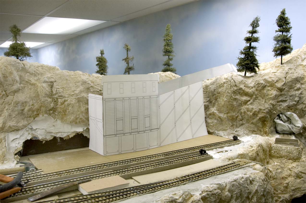 Photo 3 After the rock work was completed, a paper mock-up of the proposed ore bin and the conveyor building with it’s timber trestle bents was set in place to visualize how things would look. The 1/2" thick Gator Board base has also been cut and installed on the site. | 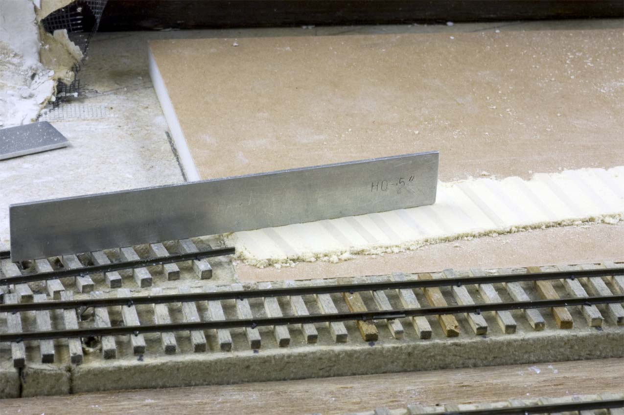 Photo 4 A new track centerline was drawn on the Gator Board, then bass wood ties cut and glued in place. The previously laid square bass wood ties I cut myself are evident in this photo. Because the Gator Board was slightly thicker than the original Homasote sub-road bed, the newly placed ties had to be sanded to the same height as those on the spur leading to the bunker. A metal straight edge from my HO layout period was used to check their height during the process. |
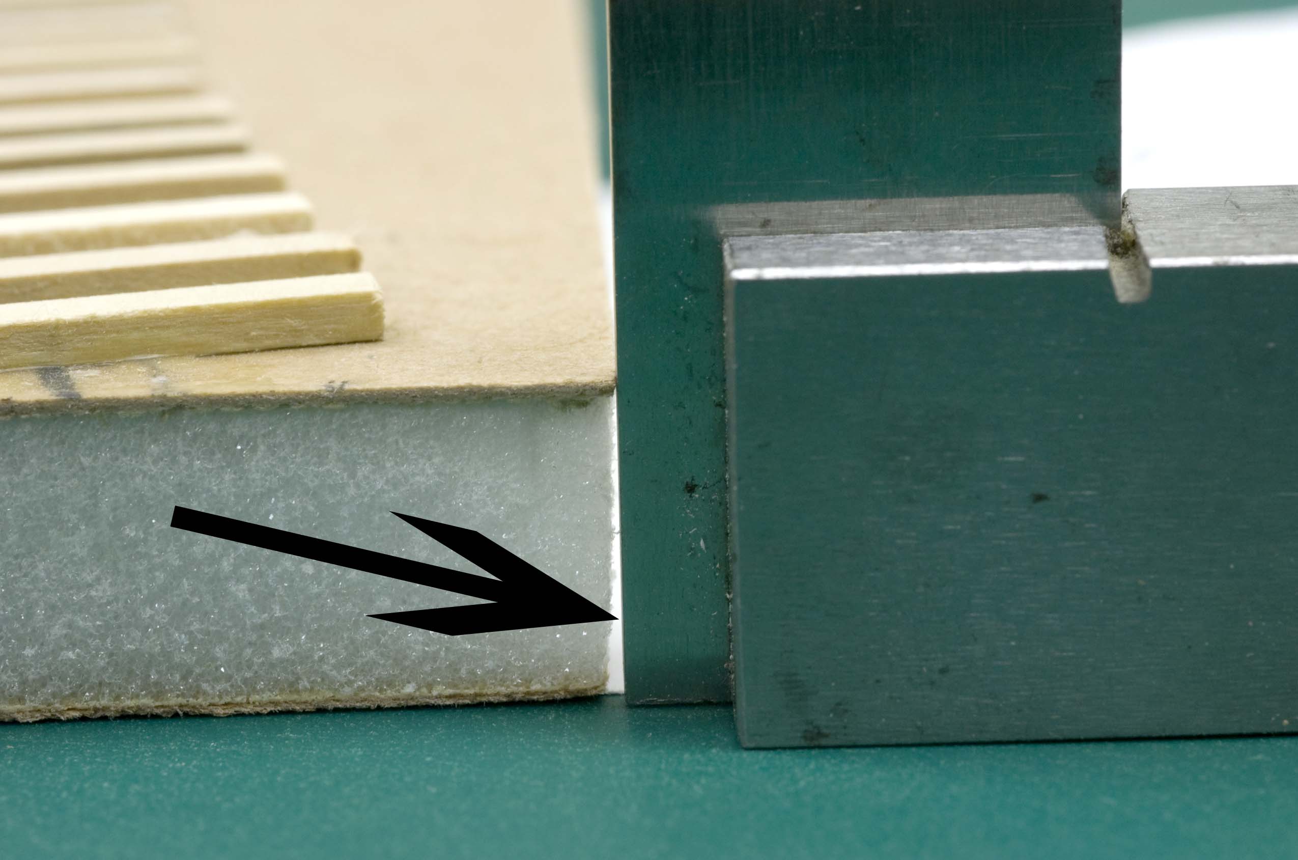 Photo 5 The edges of the Gator Board were cut at approximately a 5 degree angle with a table saw to make it easier to remove it from the layout once it became surrounded with plaster which would be added later. The slight angle is visible when checked with a machinist square. | 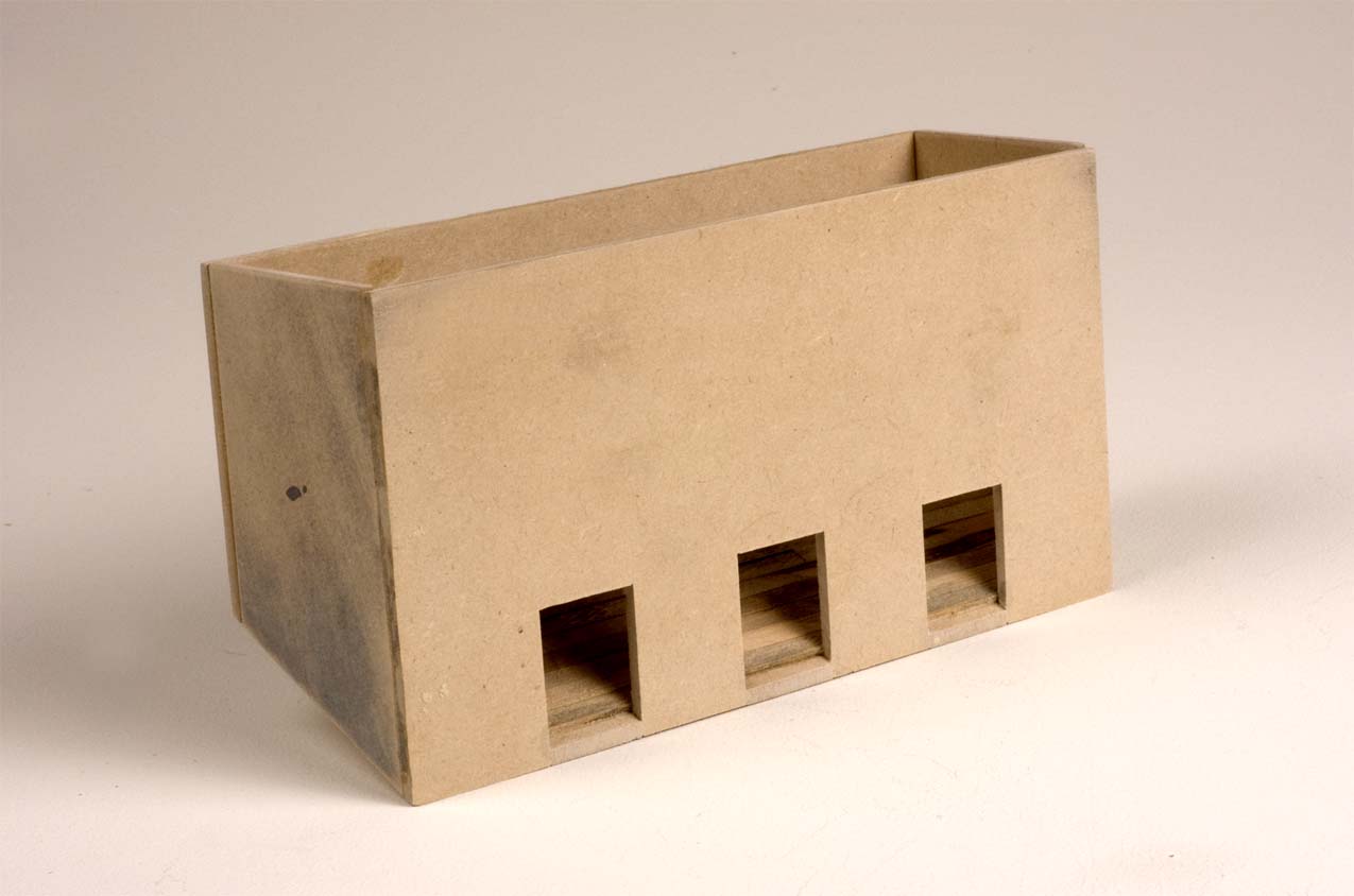 Photo 6 The inner structure of the bunker was made from untempered Masonite, or fiberboard. Its size and shape was determined with paper templates created with CadRail. The interior flooring of the bunker has already been covered with stained stripwood because the interior might be visible when the bunker doors were raised. |
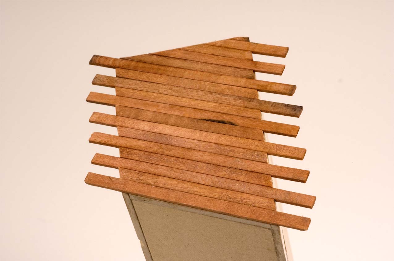 Photo 7 Pieces of scale 3” x 12” were glued to the exterior of the bunker shell. They were colored with, “Outhouse,” stain from Timberline Scenery Company. My initial plan called for the alternating pattern with long and short boards was necessary because I thought they would be attached to large timbers supporting the bunker. However, I ended up trimming them flush with both the front and back faces. | 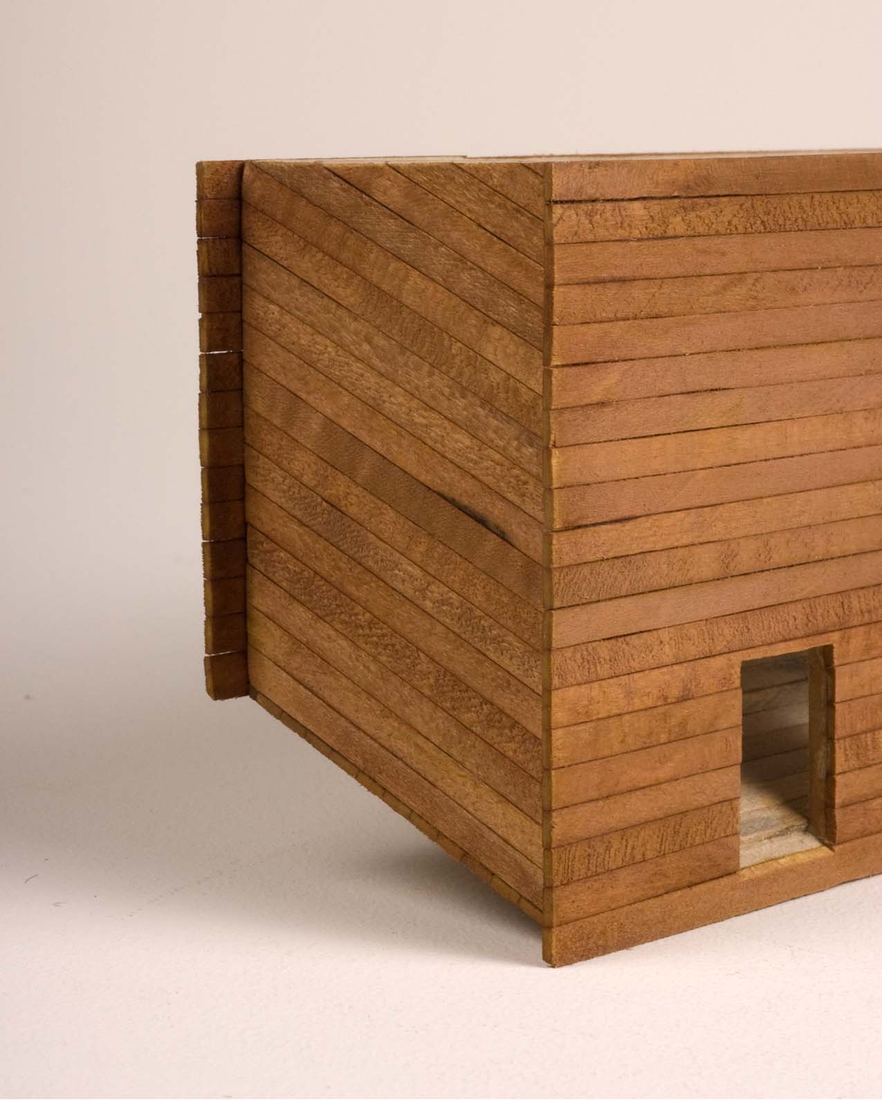 Photo 8 All faces of the bunker have now been covered with the stained stripwood. The front and rear stripwood pieces extend beyond the ends to provide a surface to attach the large framing timbers which would be added later. |
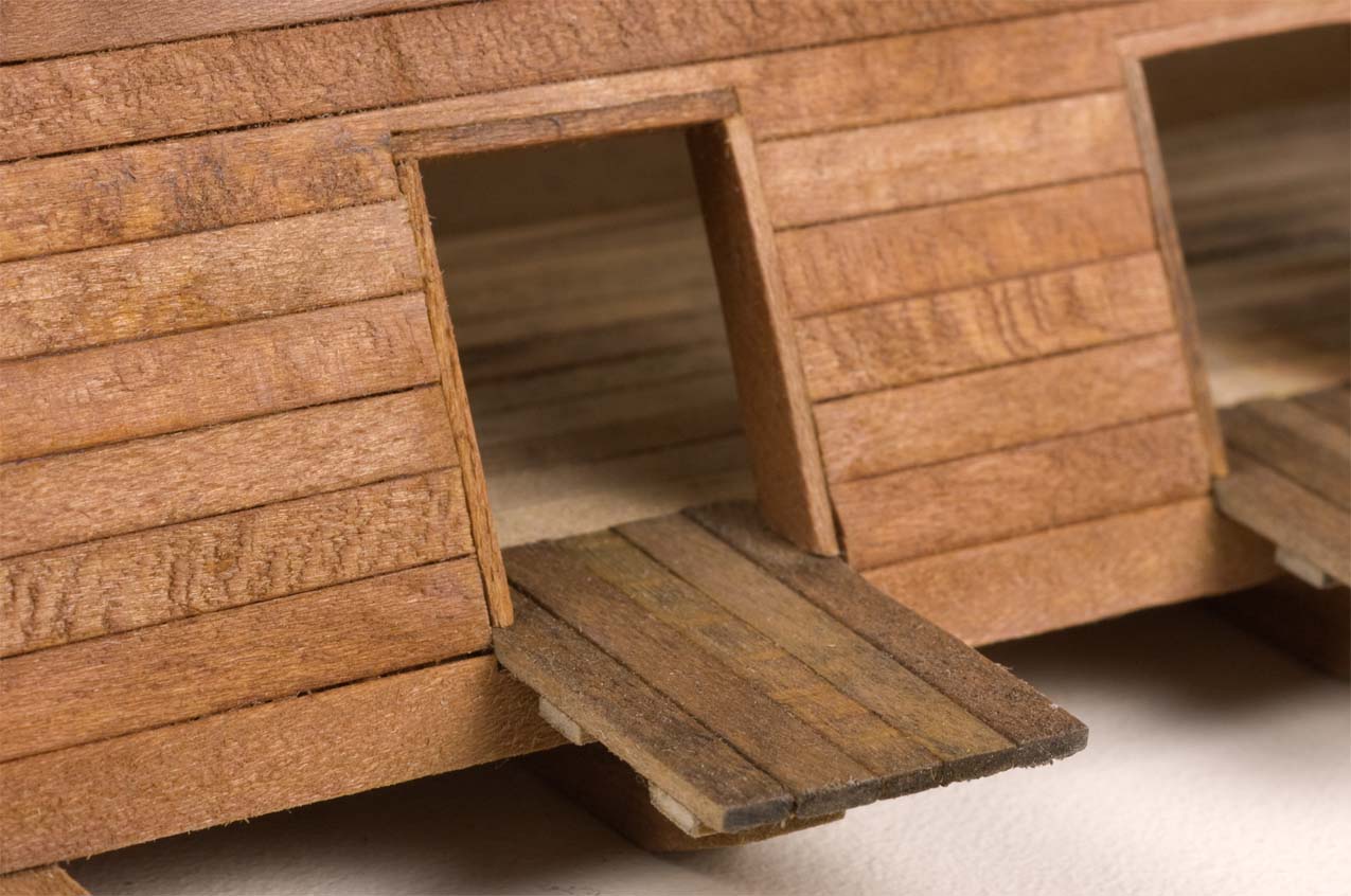 Photo 9 Three chute floors were fabricated from pieces of stripwood and test fitted into their respective openings. Once their fit was correct, they were removed so they wouldn’t be damaged. Also note that vertical and horizontal framing that has been added to the chute openings. The stripwood planks glued earlier to the bunker floor are move visible in this photo. | 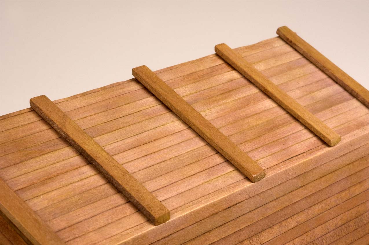 Photo 10 Five supporting timbers were cut and glued to the bottom of the bunker assembly. Before staining with the, “Outhouse,” colored stain, their ends were trimmed flush with the front and rear wall faces. |
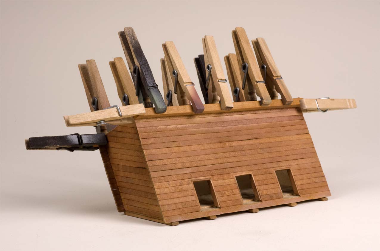 Photo 11 Wooden clothes pins make great gluing clamps. Several were used here to hold the square framing timbers in place after they were glued to the bunker face. | 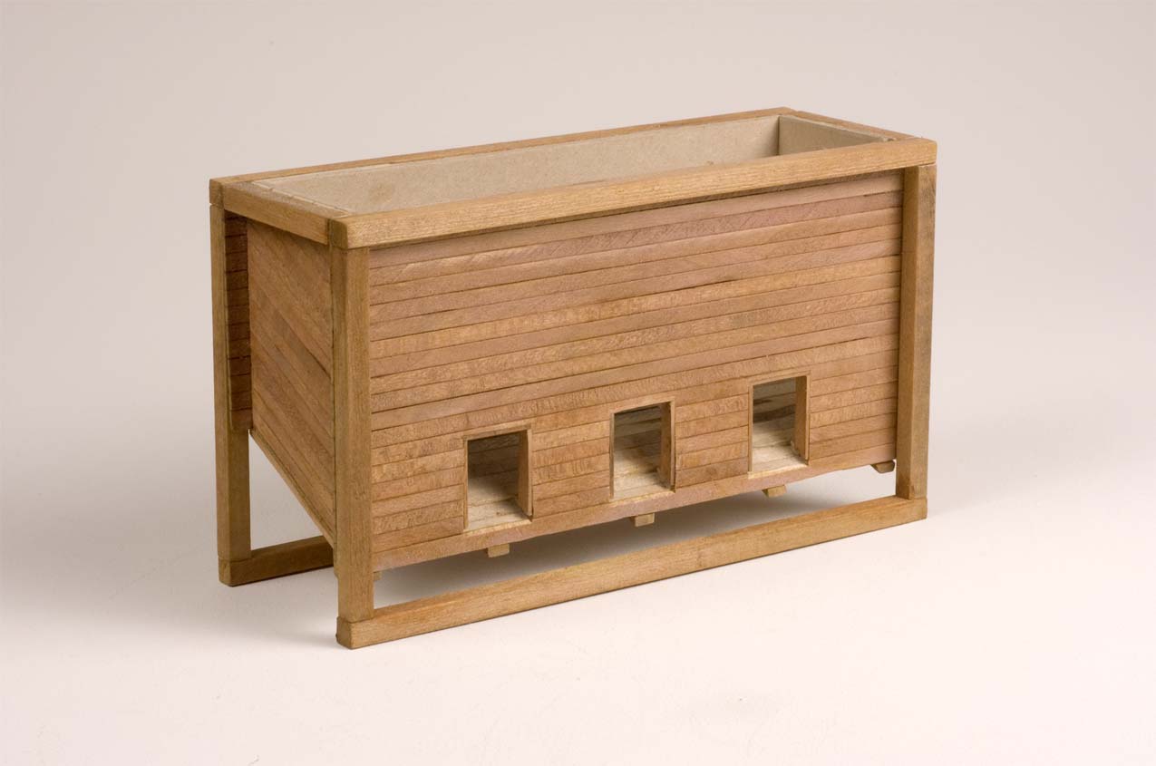 Photo 12 The main vertical and horizontal support timbers have been attached and pinned together with extremely small wire brads for additional strength. I normally utilize small brads or brass pins to reinforce the glue joints. At this point, it’s beginning to look like an ore bunker. |
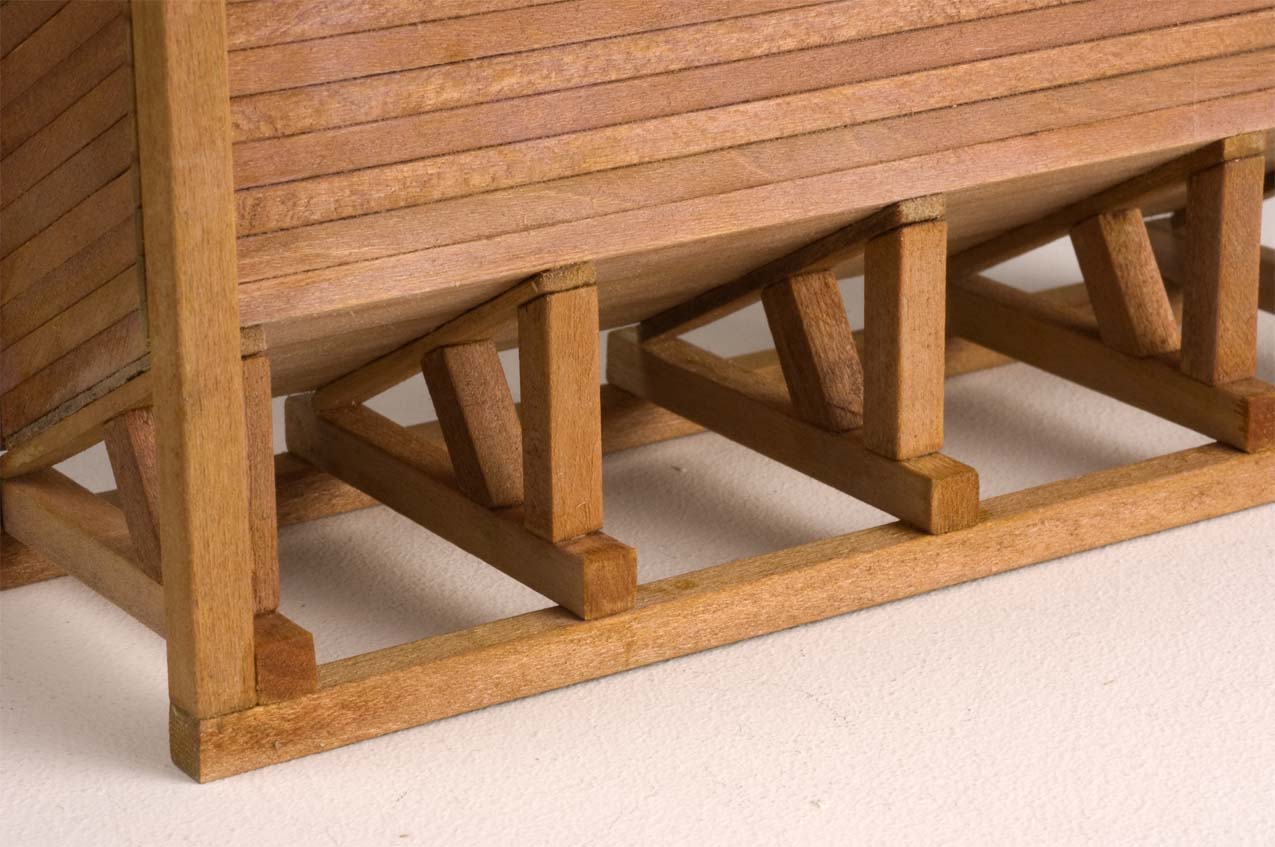 Photo 13 The five cross timbers have been installed as well as the supporting components for the bottom of the bin. These were cut from the same square stock as the main support timbers because they would be holding the entire contents of the bin. | 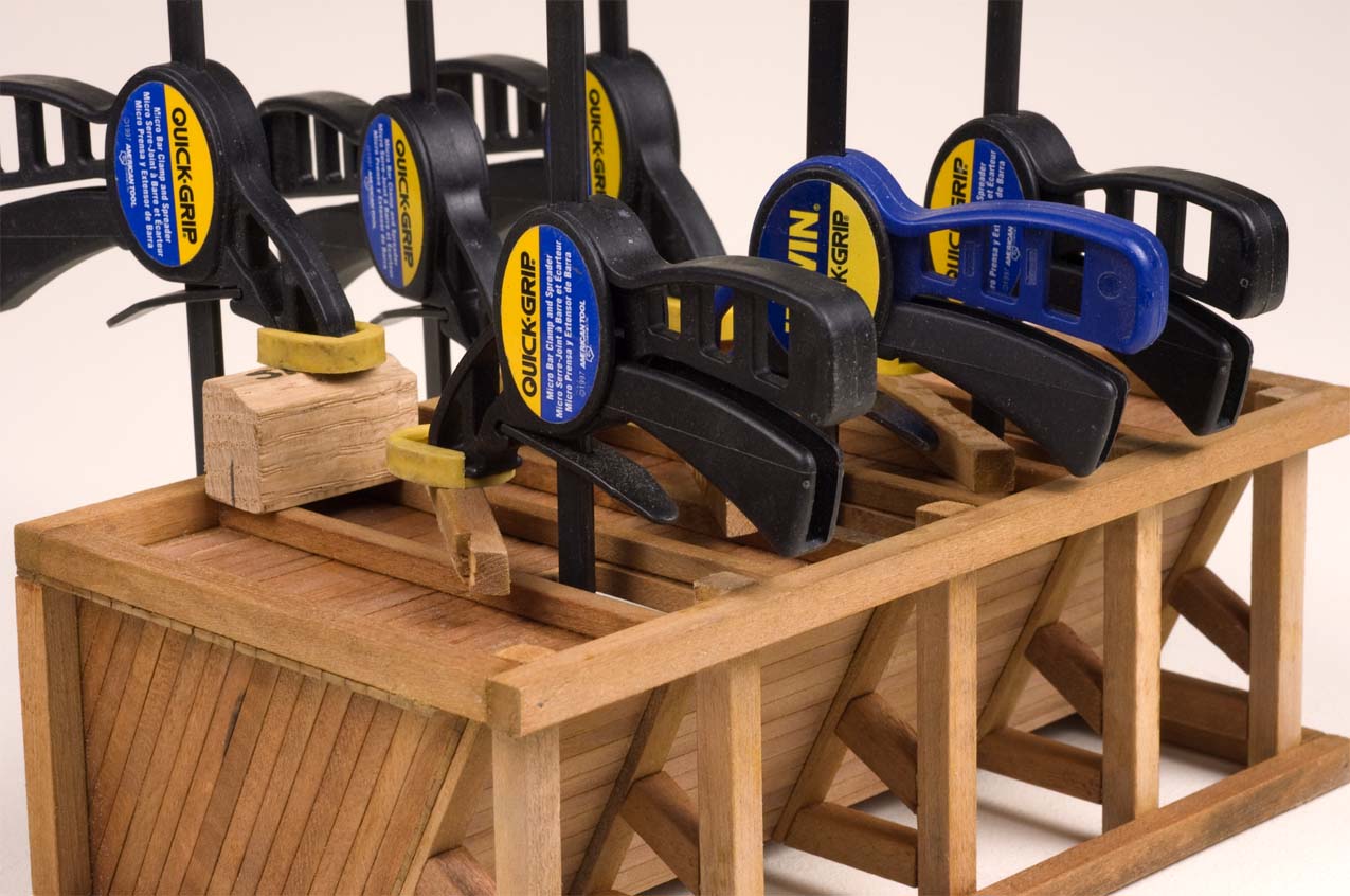 Photo 14 Many, micro sized, “Quick -Grip,” clamps and scrap pieces of wood were used to secure the smaller vertical timbers to both the front and rear faces of the bunker. I have twenty of these clamps and often times discover that I still could use more. |
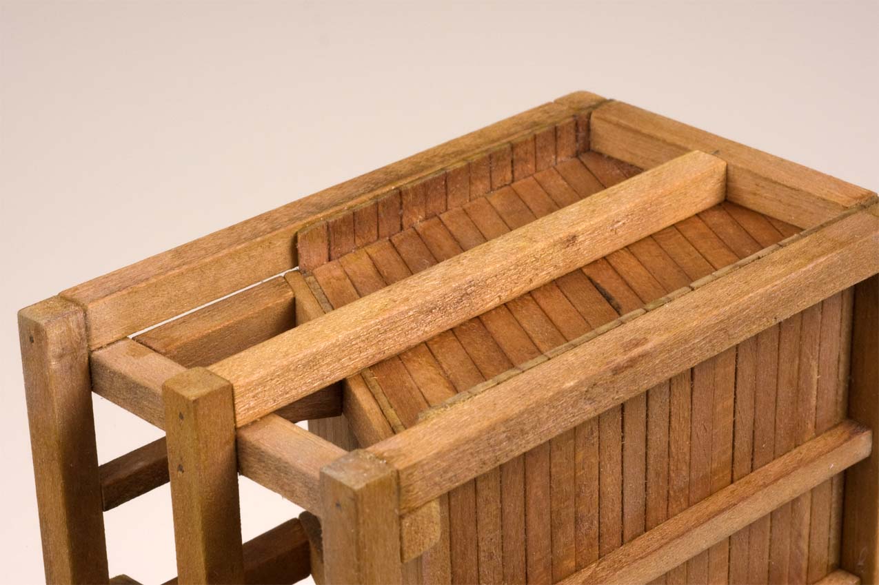 Photo 15 Vertical and horizontal support timbers have been added to the bunker. The heads of the tiny brads can be seen where they were driven through the face of one timber into the end of the other. | 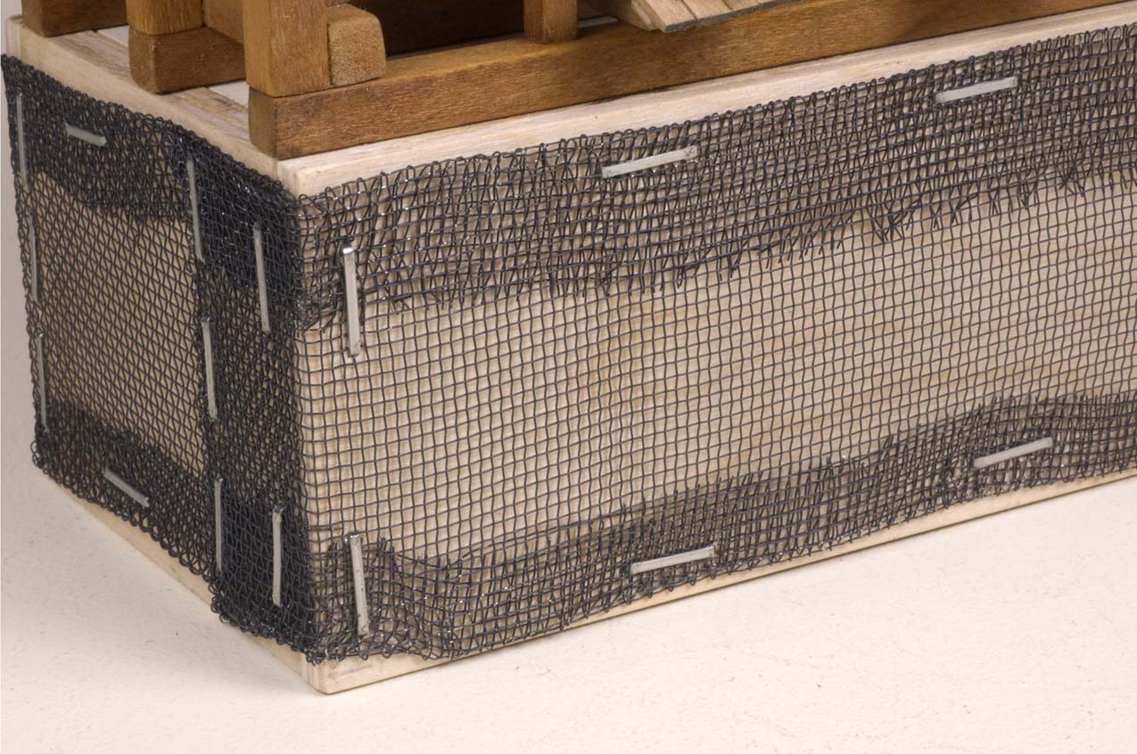 Photo 16 Rather than having a timber frame supporting base, I decided to make one out of cut stone. A box was constructed from 1/4” floor underlayment board. Plastic screen was stapled to the sides to provide a surface for the dental plaster that would be applied next. Another piece of the underlay board was attached flush with the top of the box to provide a surface for the tipple framing. |
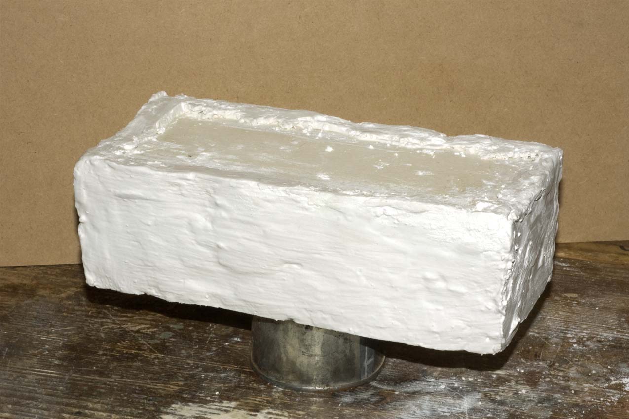 Photo 17 Dental plaster has been applied to the screen with a putty knife, building it up to at least a 3/8” thickness. An upper ridge of about 1/4” thick was added around the top edge to be carved into stones. Beauty wasn’t the goal here, but merely to have enough thickness to carve in stones without exposing the screen material. The flat space in the center is where the tipple framing will be placed | 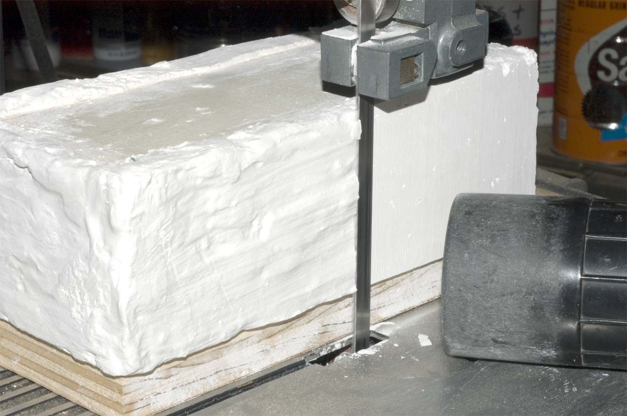 Photo 18 Once the plaster was dry, the box was temporarily secured to a scrap of plywood. The sides were then sawn smooth with my bandsaw using a 1/2” blade. The nozzle of a Shop-Vac was held close to the blade to catch the plaster dust that was created. |
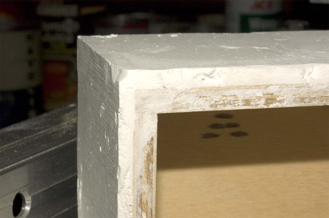 Photo 19 The plaster is slightly less than the thickness of the underlayment board. The surface marks from the band-saw blade are still visible, but were removed by gently sanding them with sand paper, then wiped with a damp cloth to create an irregular surface. The faces were then ready for carving the stone block shapes. | 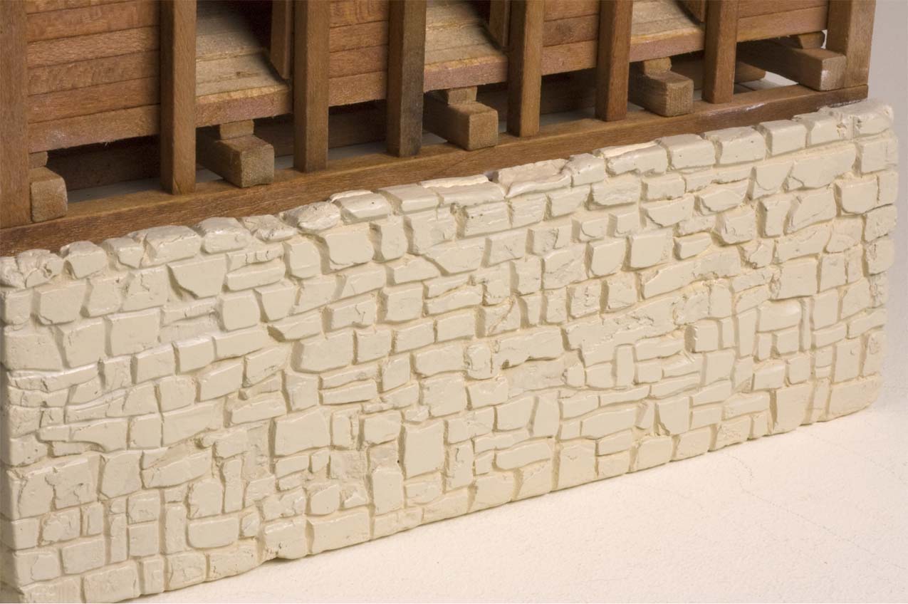 Photo 20 Individual stone faces were carved into the plaster using dental explorers, carbide tipped scribes, knife points and hack saw blades. Stone blocks were carved into the corners to create an interlocking pattern. When finished, the plaster was sprayed with Krylon, “Almond,” colored satin finish paint. The satin finish provided a hard, protective coating for the plaster and offered a smooth surface for the acrylic craft paints that would be used later to color the individual stones. |
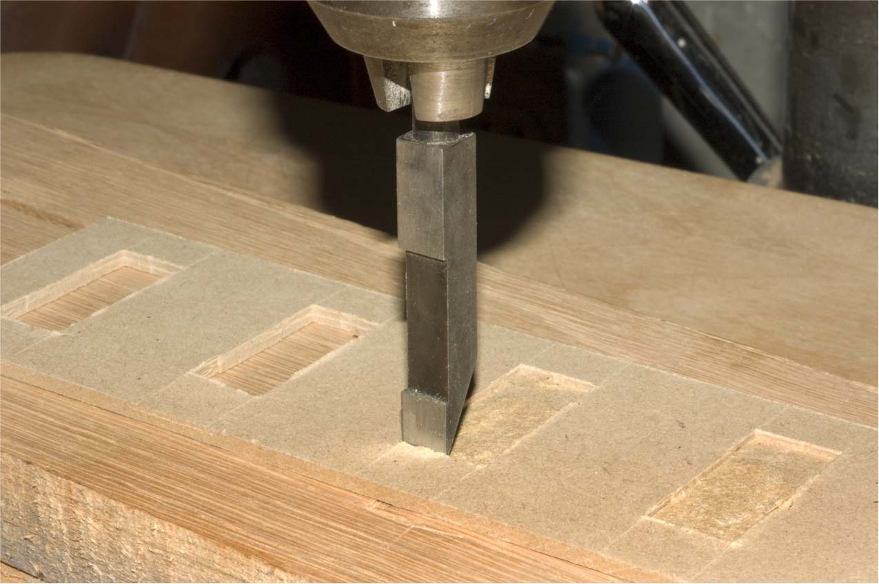 Photo 21 A corner cutting tool purchased from Micro-Mark was used to cut the door and window openings in the head house walls. The tool was mounted in my drill press and pressed downward into the fiber board to, "nibble,” away the excess material. Please note that the drill press WAS NOT running but simply used to push the cutting edges of the tool through the fiber board. | 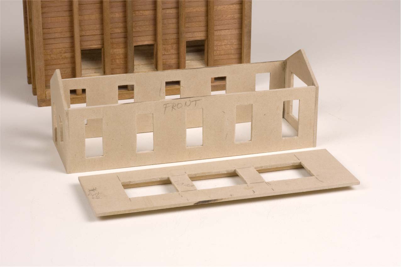 Photo 22 A head house for the bunker was made from the fiber-board, using templates created with CadRail. A removable floor piece was also made that sets into the opening at the top of the ore bunker. The floor piece would eventually be firmly secured to the head house walls. |
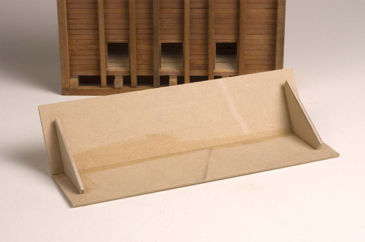 Photo 23 The removable roof for the tipple head house was also made from the 1/8” fiberboard. Two roof formers at the ends help maintain the proper pitch angle and also serve as aligning features so the roof can be easily set back in place. | 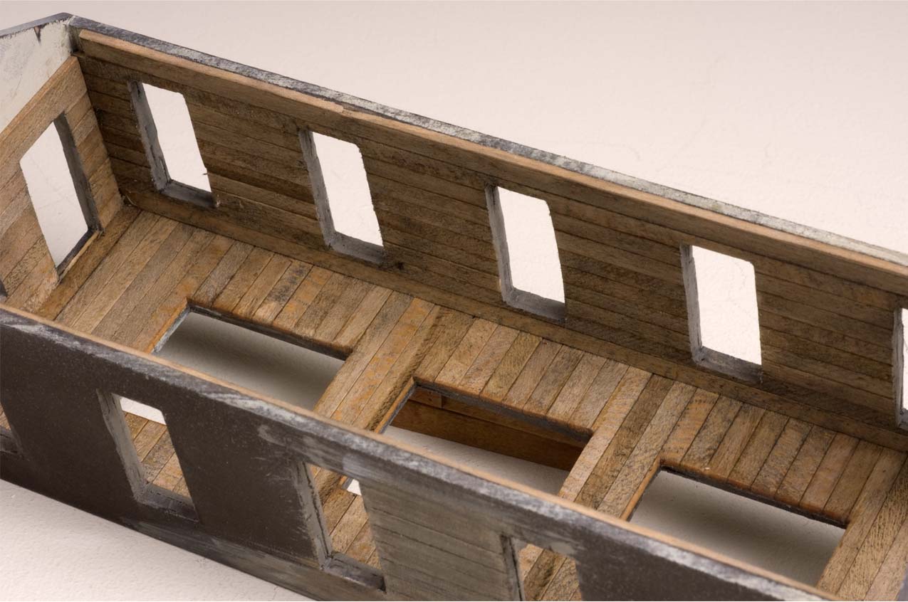 Photo 24 The floor has been glued to the head house shell with yellow glue, then completely covered with 12” scale width stripwood with, "Aleene's Tacky Glue." The flooring over the three bunker floor holes was removed with a hobby knife and its ends were sanded smooth. The same width boards were also applied horizontally to the interior walls. After the excess material was removed from the window and door openings their inner edges were also sanded smooth with a sanding stick. |
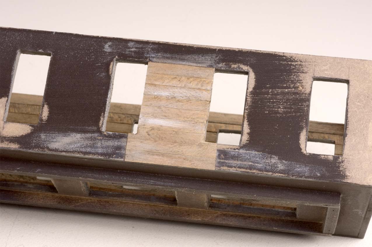 Photo 25 The exterior of the bunker head house would be covered with black craft paper to represent tar paper. I wanted to have some of the underlying boards visible where the tar paper had been damaged by the elements. A small area was milled away the same thickness of the exterior stripwood using a end mill in the drill press and carefully working it until I had removed enough material. I extended the boarded up area a little past the area where the edges of the torn paper would be because the ends of the boards would be covered with the craft paper. Square pieces of stripwood were also glued to the underside of the floor to help with its alignment when the head house was reinstalled or seated back onto the bunker. | 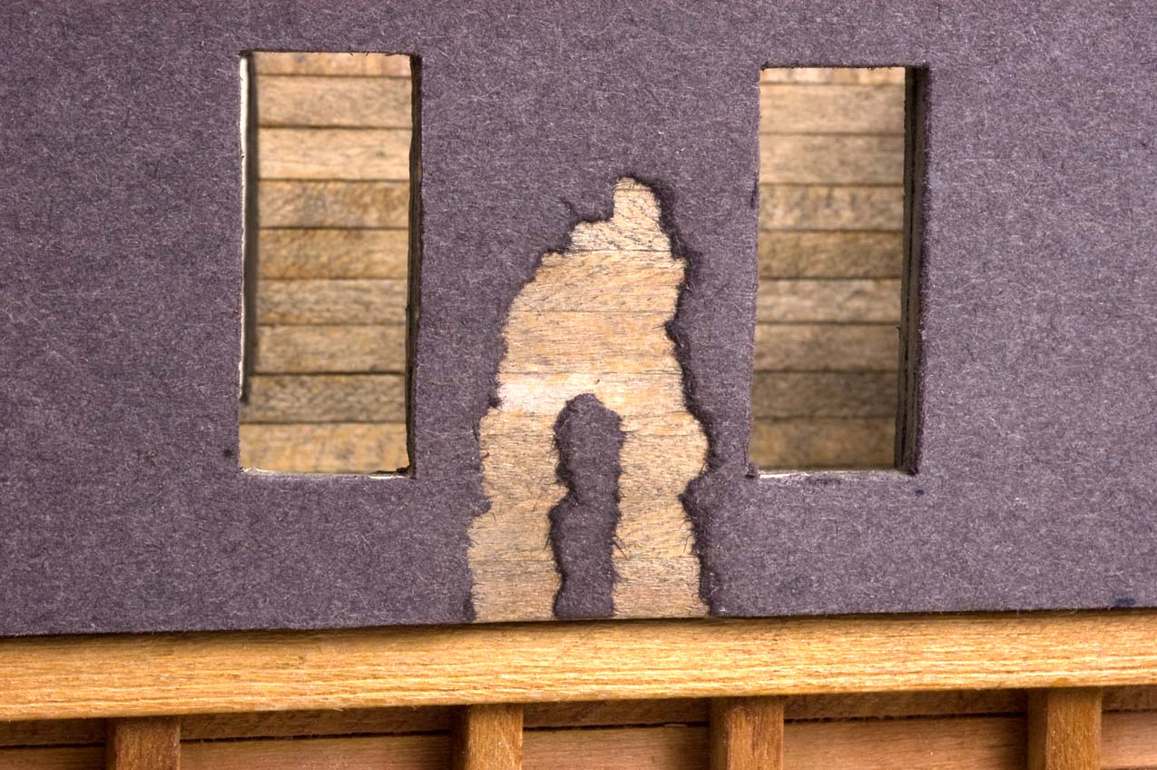 Photo 26 Here’s a closer view of the area with the torn craft paper siding. The stained stripwood is clearly visible below the paper. |
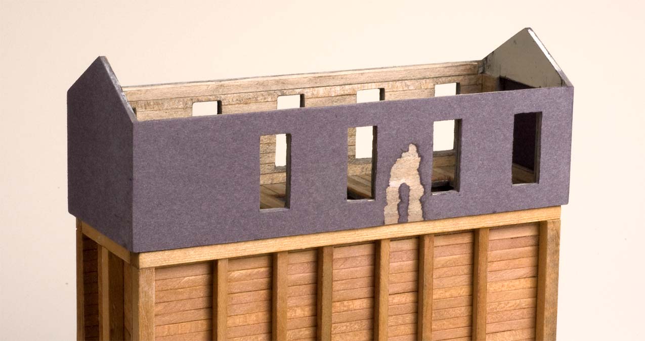 Photo 27 The exterior walls of the bunker head house were covered with black craft paper to represent tar paper. It was carefully torn around the area where the stripwood was glued so that the underlying siding could be seen. The paper still needs to be removed from some of the window and door openings. | 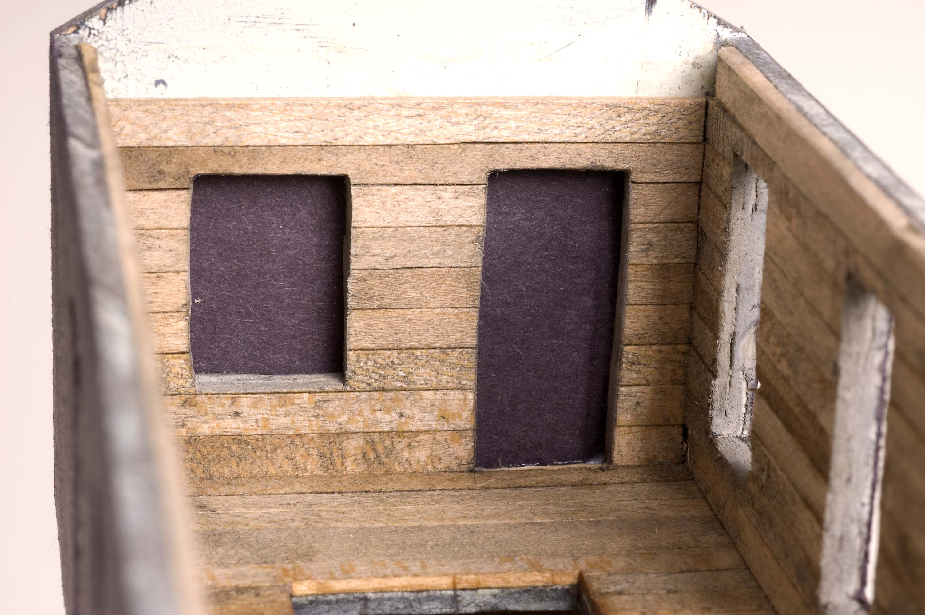 Photo 28 The interior wall boards are visible here as well as the black paper that still needs to be removed. |
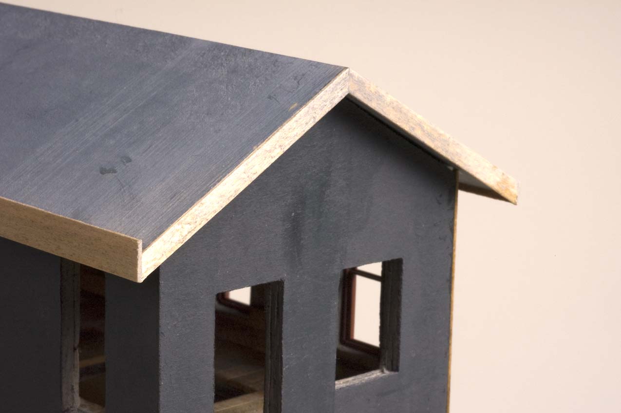 Photo 29 Pieces of stripwood have been glued to the ends and long edges of the roof component. Note that the piece on the front edge extends above the roof surface. | 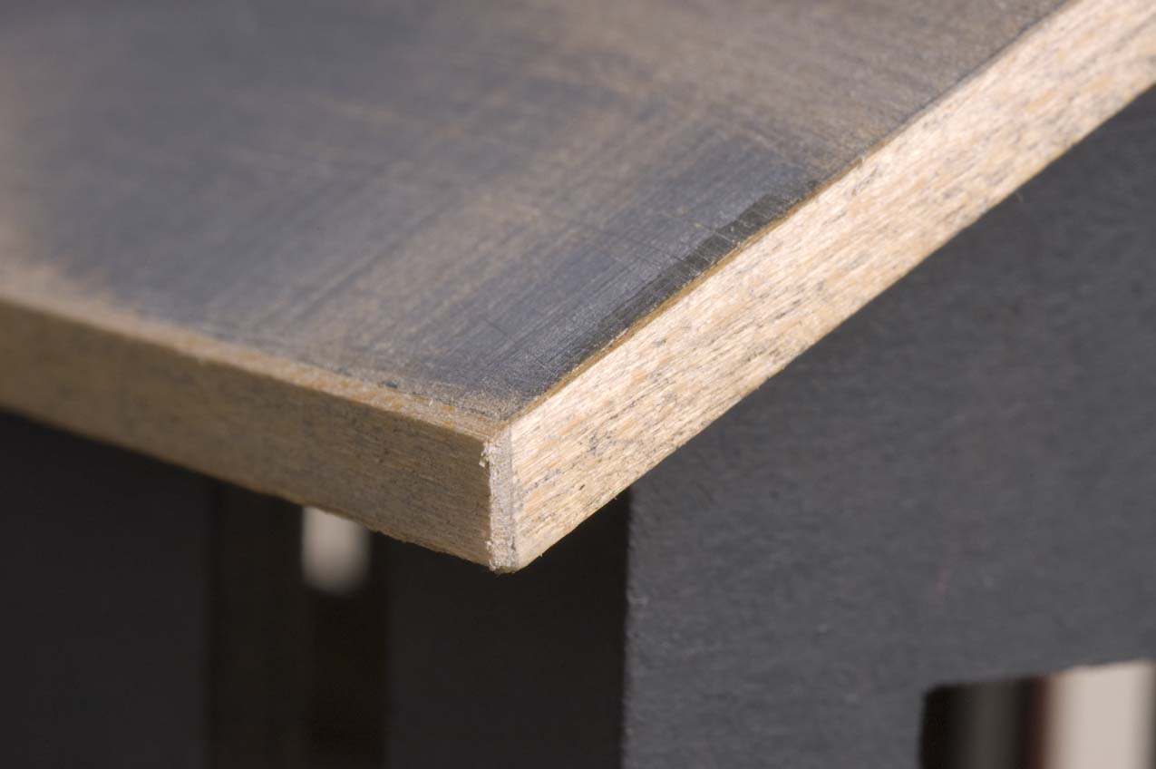 Photo 30 The stripwood material that extended above the roof surface has been removed with a sanding stick to make it even with the roof surface. |
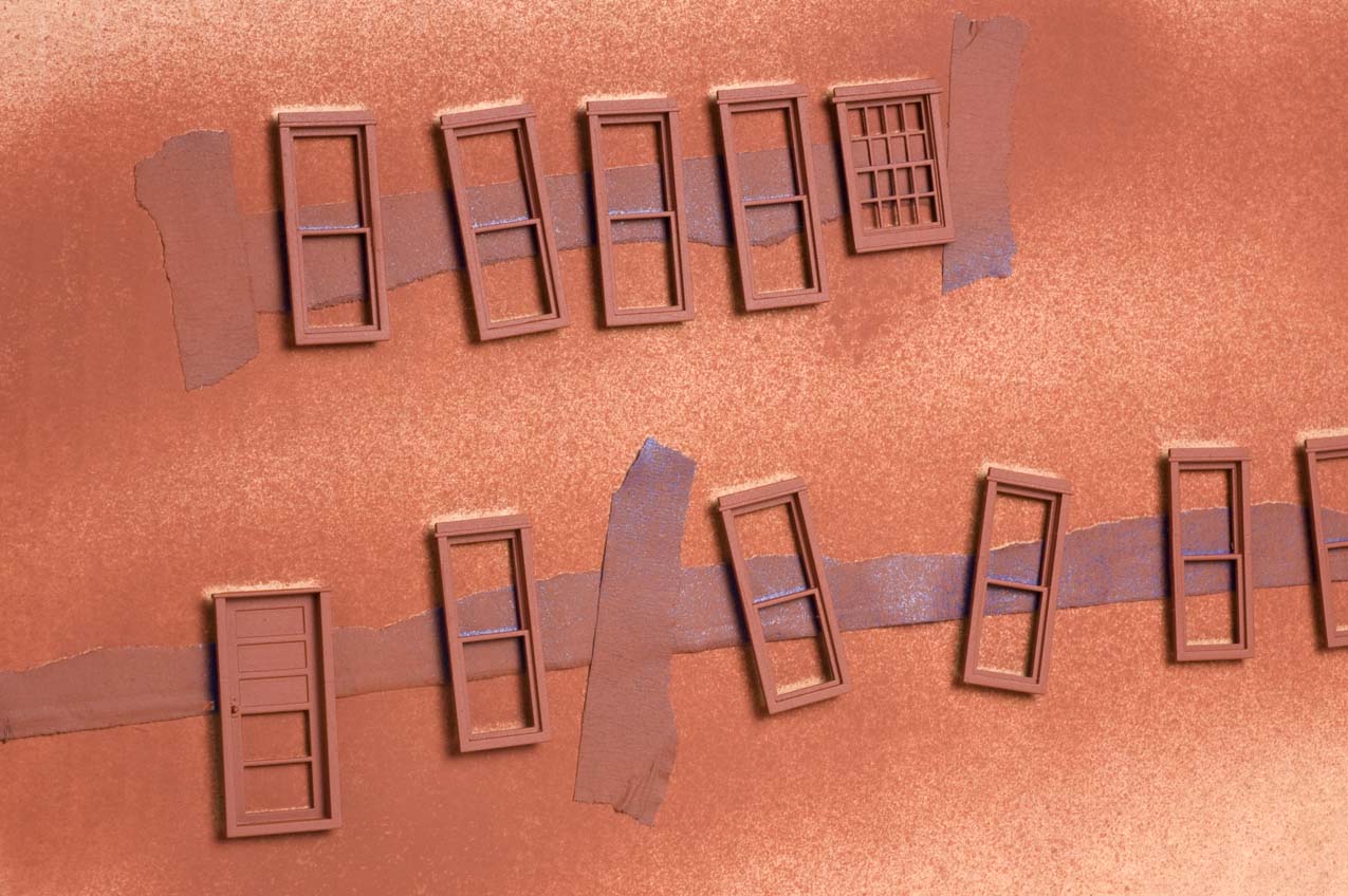 Photo 31 Grandt Line S scale double hung windows and door castings were first painted with Krylon, “Ruddy Brown Primer,” then lightly dry brushed with white acrylic craft paint. | 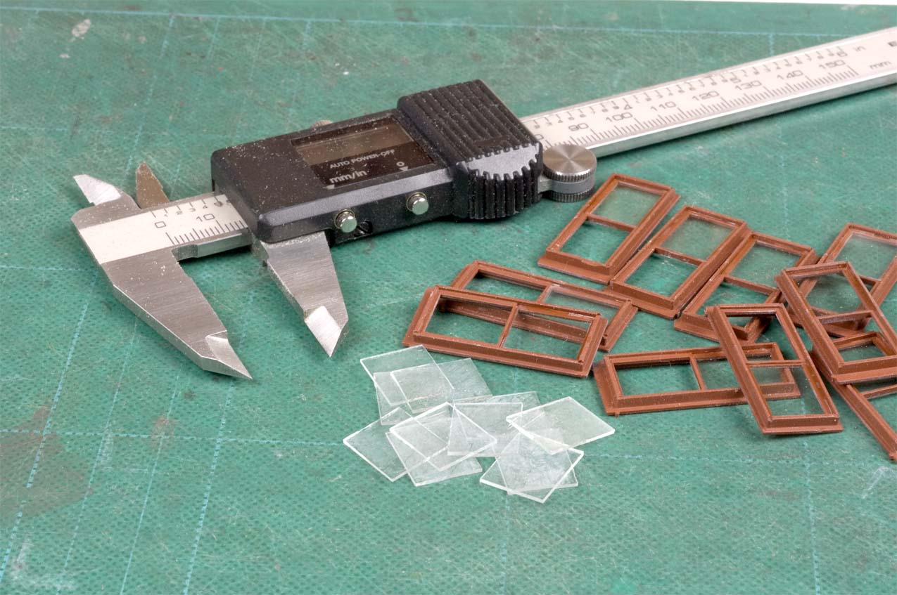 Photo 32 Calipers were used to measure the glazed areas on the window and door castings. Those measurements were then used to scribe and cut 1/32” thick glass that came from 35mm glass slide mounts. |
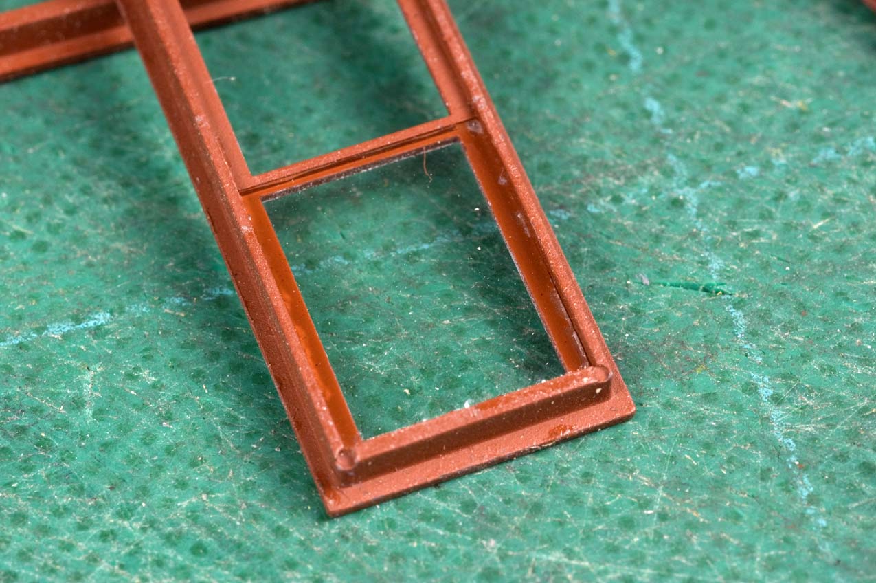 Photo 33 This close up view shows the glass panes glued in place with Dr. Mike’s #2 CA in one of the window castings. | 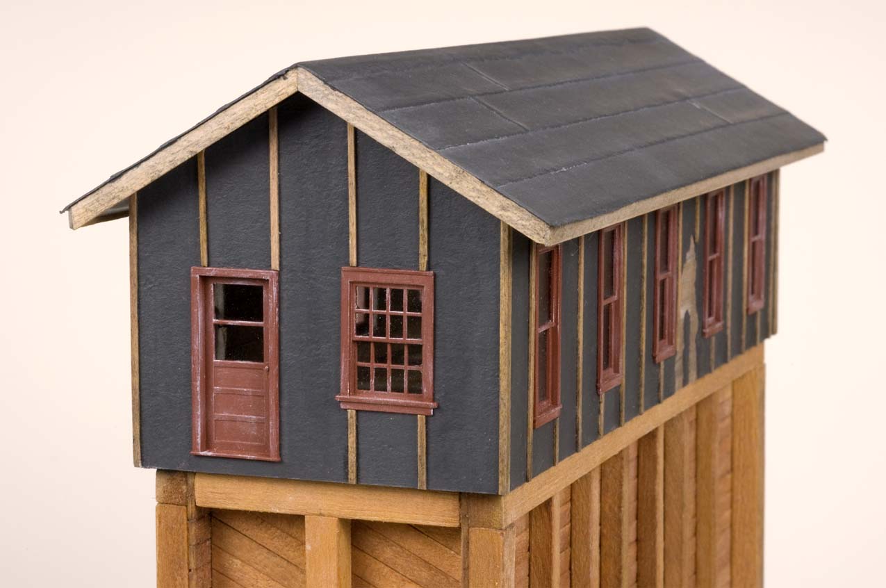 Photo 34 The windows and door have been inserted into their respective openings and secured in place with carefully applied dots of the CA. The trim boards along the ends and long roof eave edges add a finished look to the roof piece. The roll roofing, cut to 3' wide strips from a piece of the same black craft paper used for the tar paper siding has also been attached with Aleene's Tacky Glue. The lower edges of the roofing strips have been left ragged and lapped over the preceding layer about 6 scale inches. When firmly in place, the paper was brush painted with Polly Scale, “Grimy Black,” paint. When dry, excess roofing at the ends was trimmed with a sharp Xacto knife. |
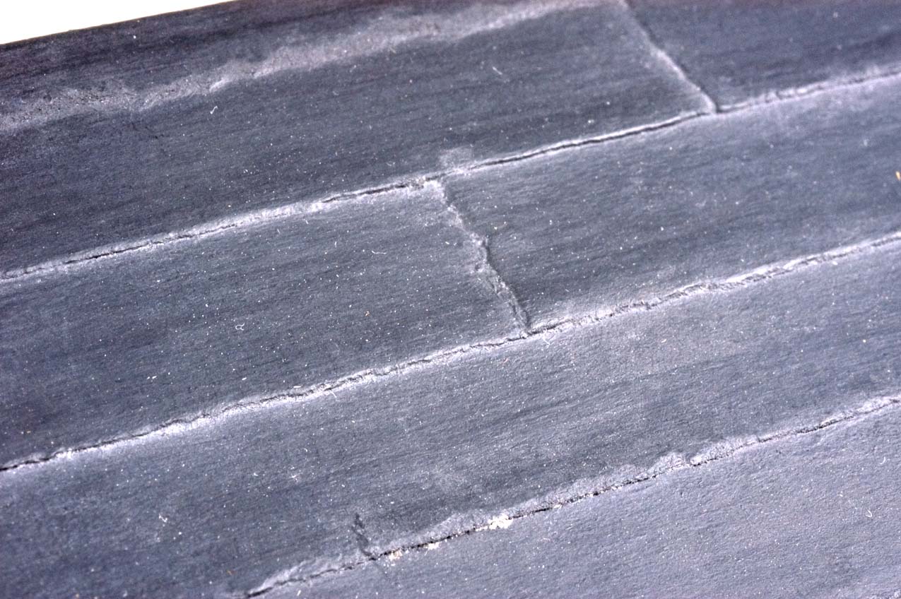 Photo 35 Here is a close up view of the roofing paper showing the ragged edges. A little bit of white chalk dust has been applied to suggest exposure to the elements. | 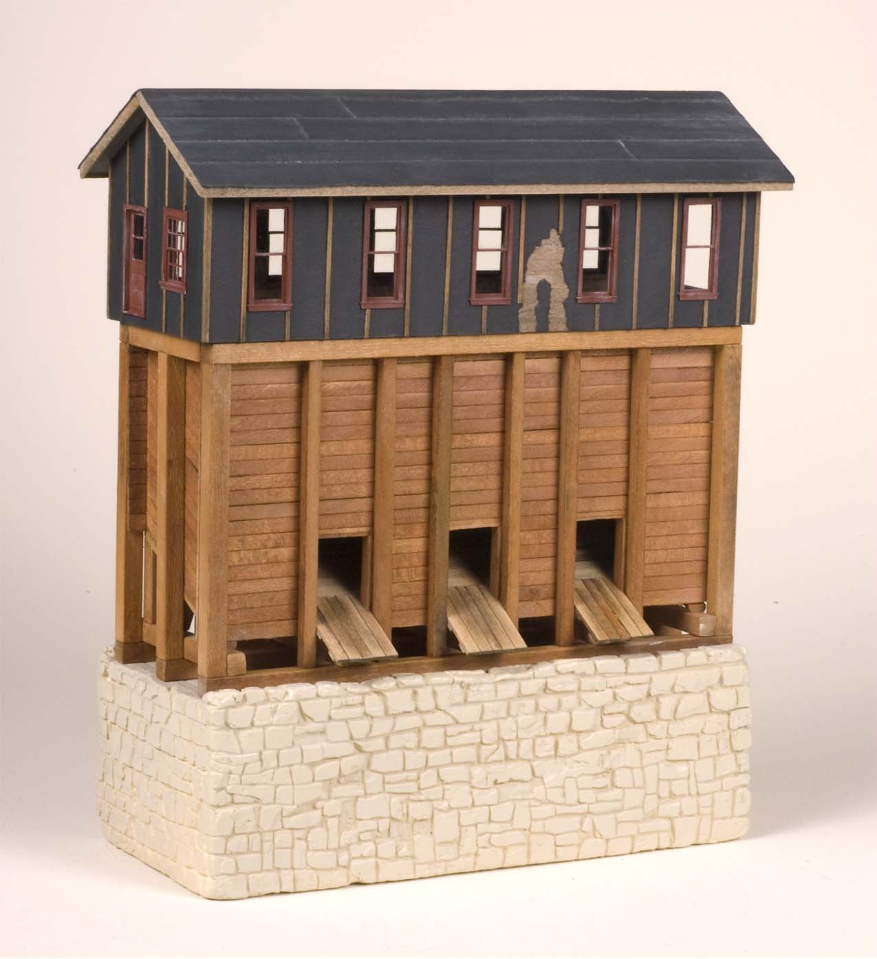 Photo 36 This view shows the plaster base, timber frame bunker and head house at this stage in the construction process. The carved stone pattern in the plaster base has been sprayed with Krylon, “Almond,” colored satin finish paint. These major components are still separate sub-assemblies and can be worked on individually. |
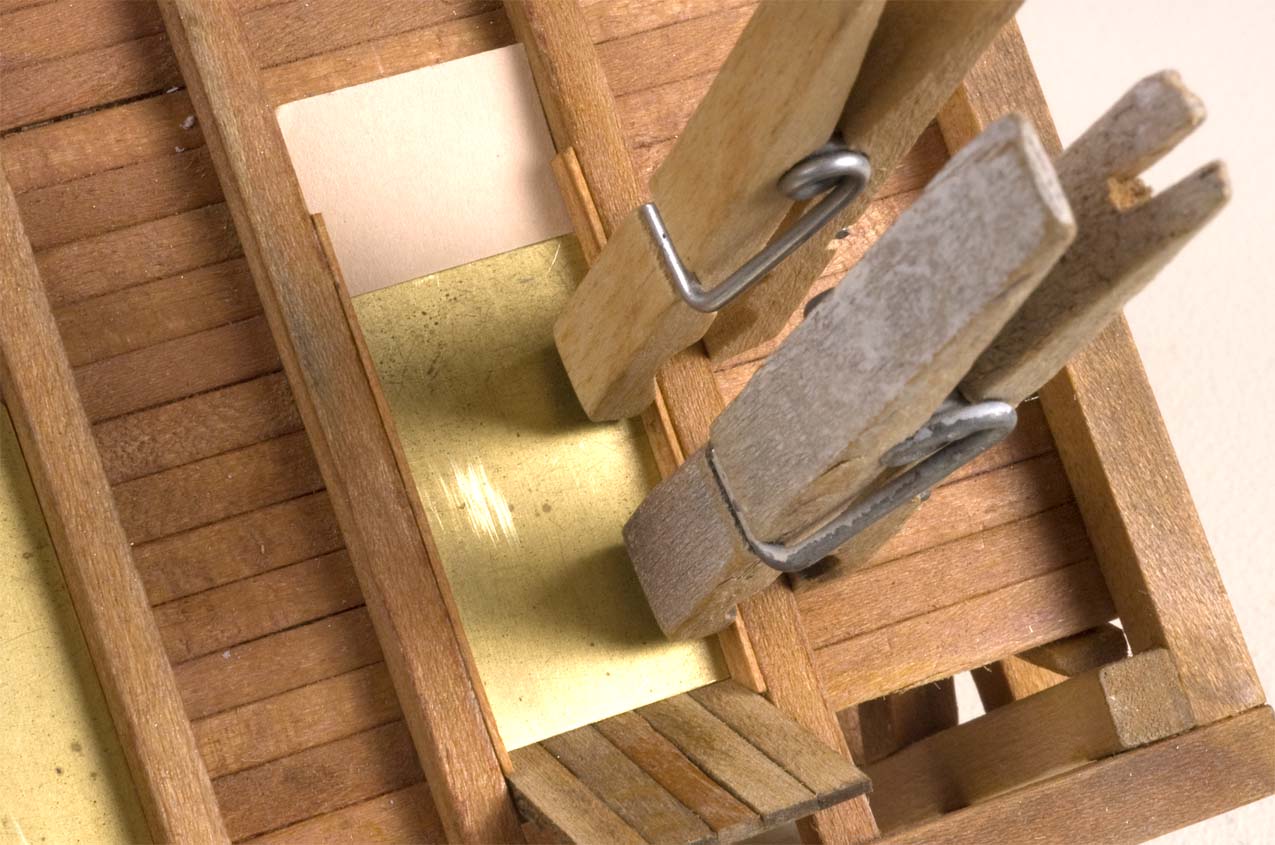 Photo 37 Thin pieces of brass shim stock were cut to fit between the 12”x 12” timbers that frame the chute openings. The brass stock simply serves as a sliding support for the chute doors. The chute doors would be added later along with the rack and pinion details. Two pieces of pre-stained 3“ x 12” wide stripwood were glued to the inner face of timbers to create retainers for the chute plates. The light colored piece of index card paper stock was temporarily placed under the pieces of brass to help locate the wood strips. When the paper was removed, there was enough space for the brass doors to be freely raised and lowered. | 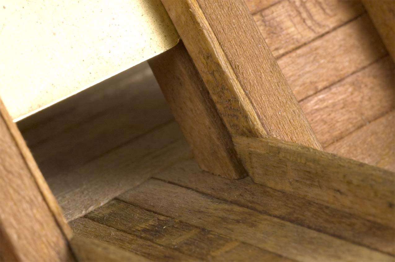 Photo 38 This view shows the slot or door guide created by the thin piece of stripwood . There’s just enough space for the brass gate to easily move up and down. |
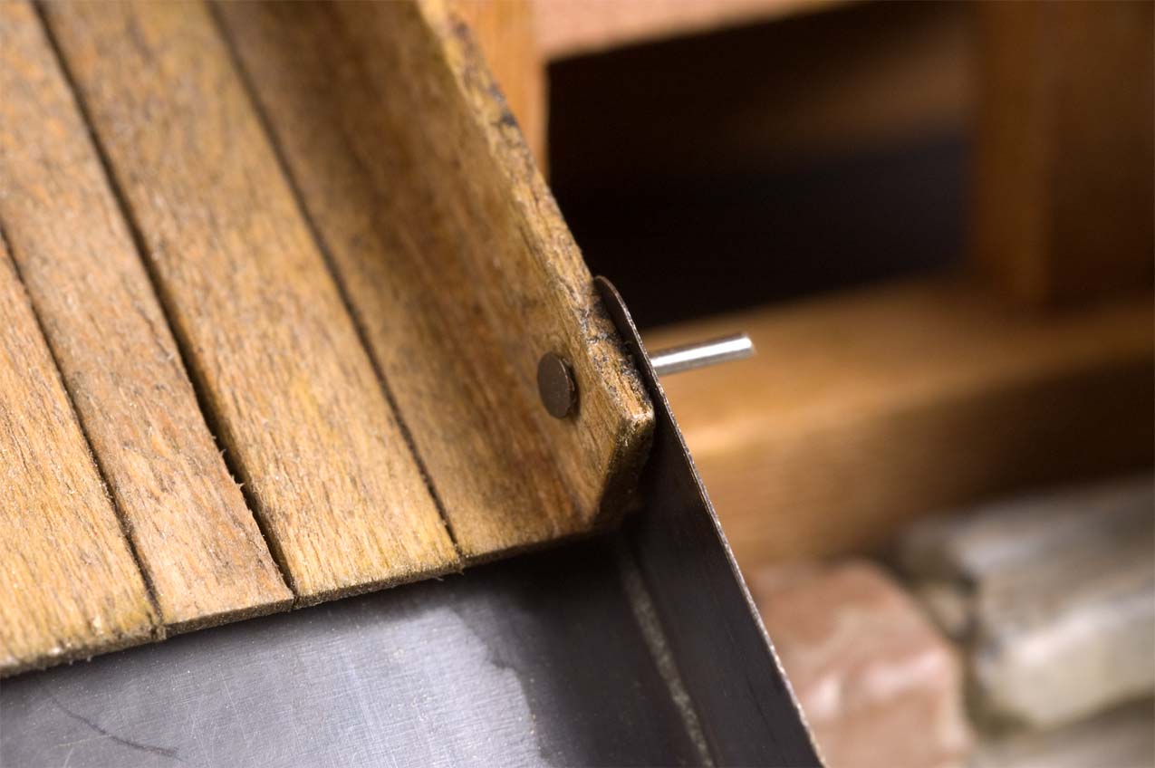 Photo 39 Tiny flat head pins I discovered in the jewelry section of a, “Hobby Lobby,” store serve as pivot points for the three movable chute pieces. These chute extensions were also made from shim brass stock and colored with Archer’s Etchant and Birchwood Casey’s Gun Bluing solutions. The same chemicals were also used to color the three movable brass bunker gates. | 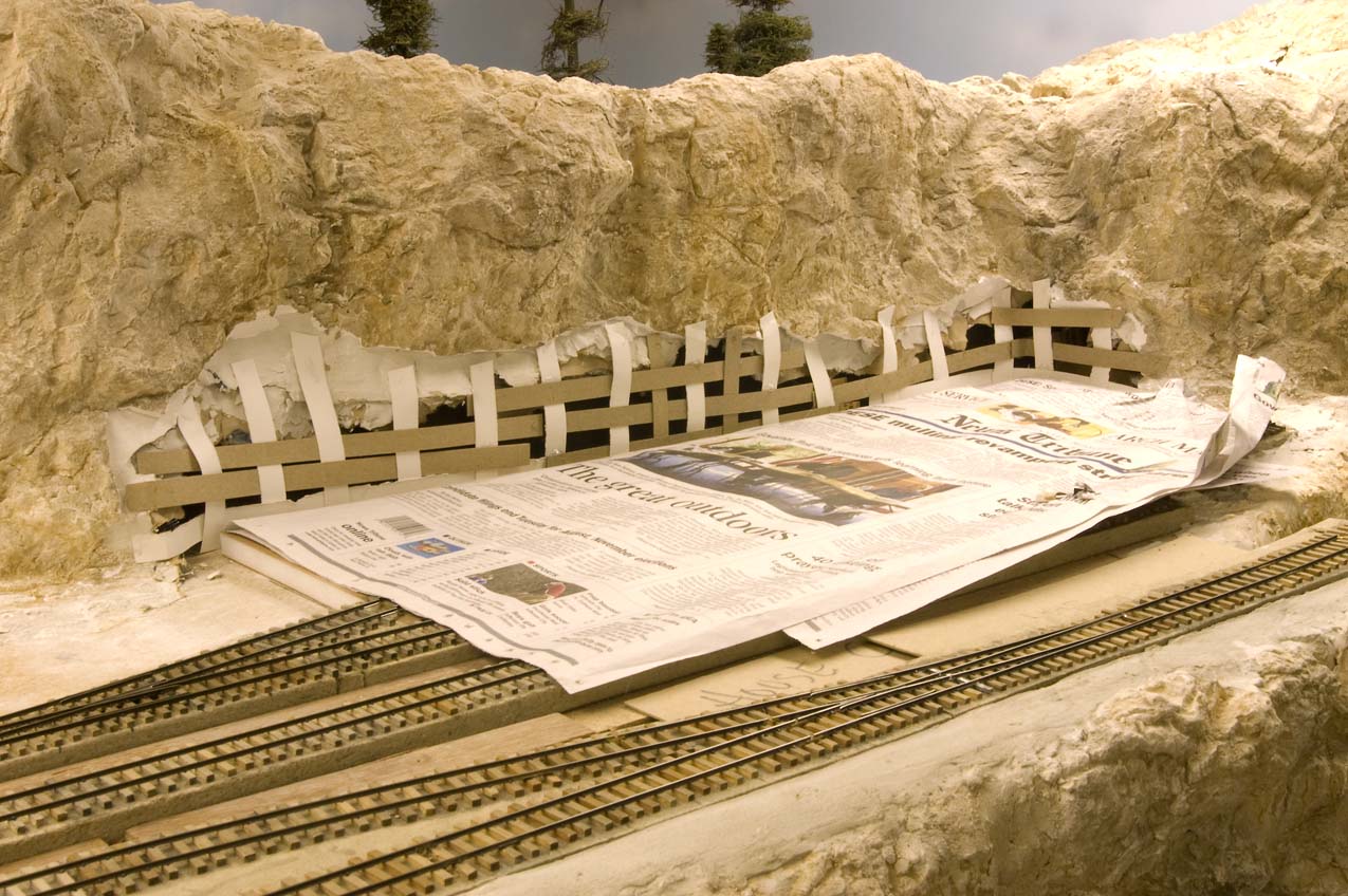 Photo 40 The bunker structure was set aside for a while a the site base was further developed. To protect the surrounding track, everything was covered with newspapers. Cardboard strips were also been added to the openings in the rock work to support the new hard shell scenery. |
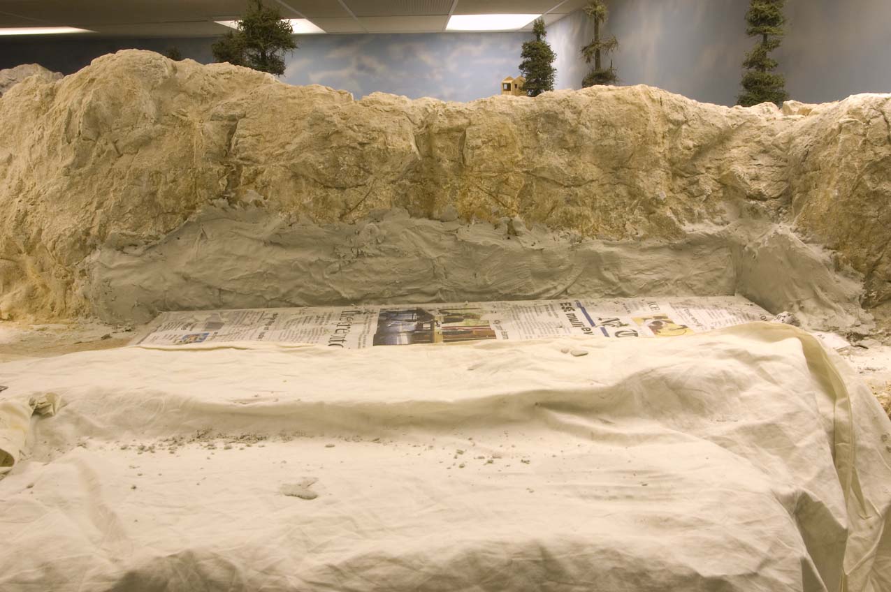 Photo 41 Torn pieces of brown shopping bags were dipped in a pancake batter consistency mix of Hydrocal B-11 plaster, then applied over the cardboard strips, blending them into the surrounding plaster. When the Hydrocal was firm, the Gator Board was removed and its angled edges were covered with clear packaging tape to prevent the plaster from sticking to them. Then it was set back in place. A thicker mix of the Hydrocal was then applied along those edges and leveled off to be even with the top of the Gator Board surface. | 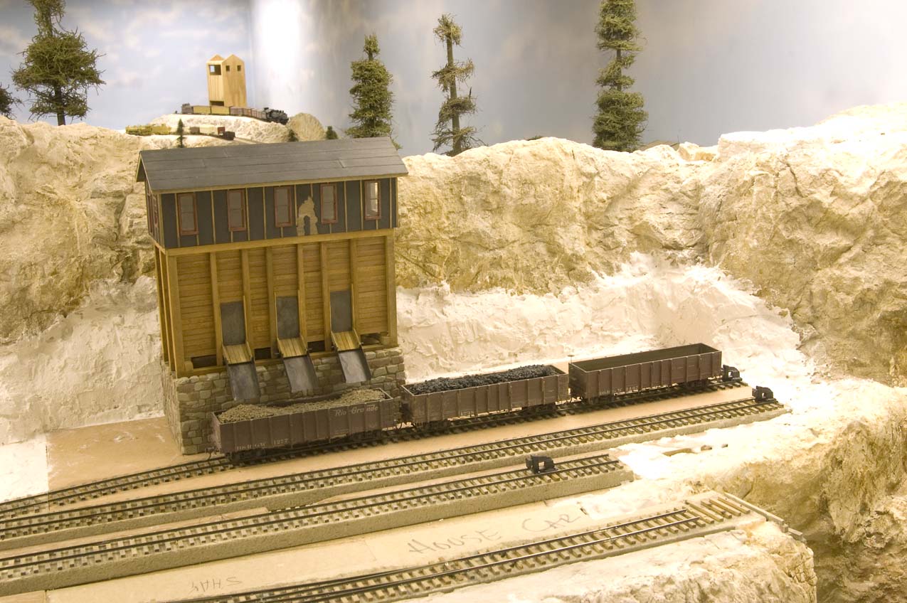 Photo 42 The mine base, bunker and head house assembly was set in place to see how things would look. The wooden ties added and sanded earlier have already been colored with an alcohol and black shoe dye stain and code 70 Micro Engineering rail spiked in place. |
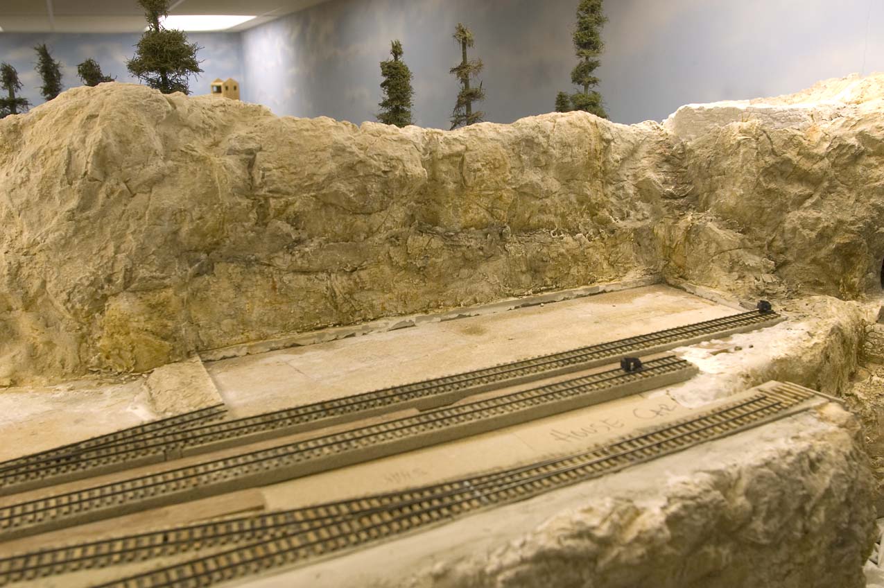 Photo 43 Because the sides of the Gator Board were angled, it's easy to remove it from the layout. With the Gator Board piece safely out of the way, the newly applied plaster was stained with acrylic paints to match the original surrounding area. | 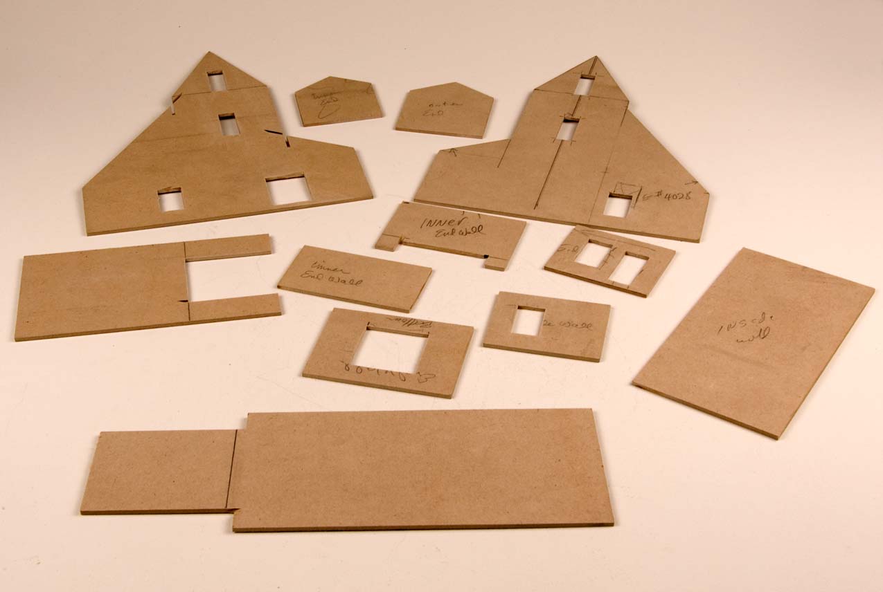 Photo 44 The mine building was tackled next. Here are the various wall and floor components that were cut on a table saw from the 1/8" fiber board using paper templates created with CADRail. The various door and window openings have already been punched out using the chisel and drill press used earlier on the bunker head house. |
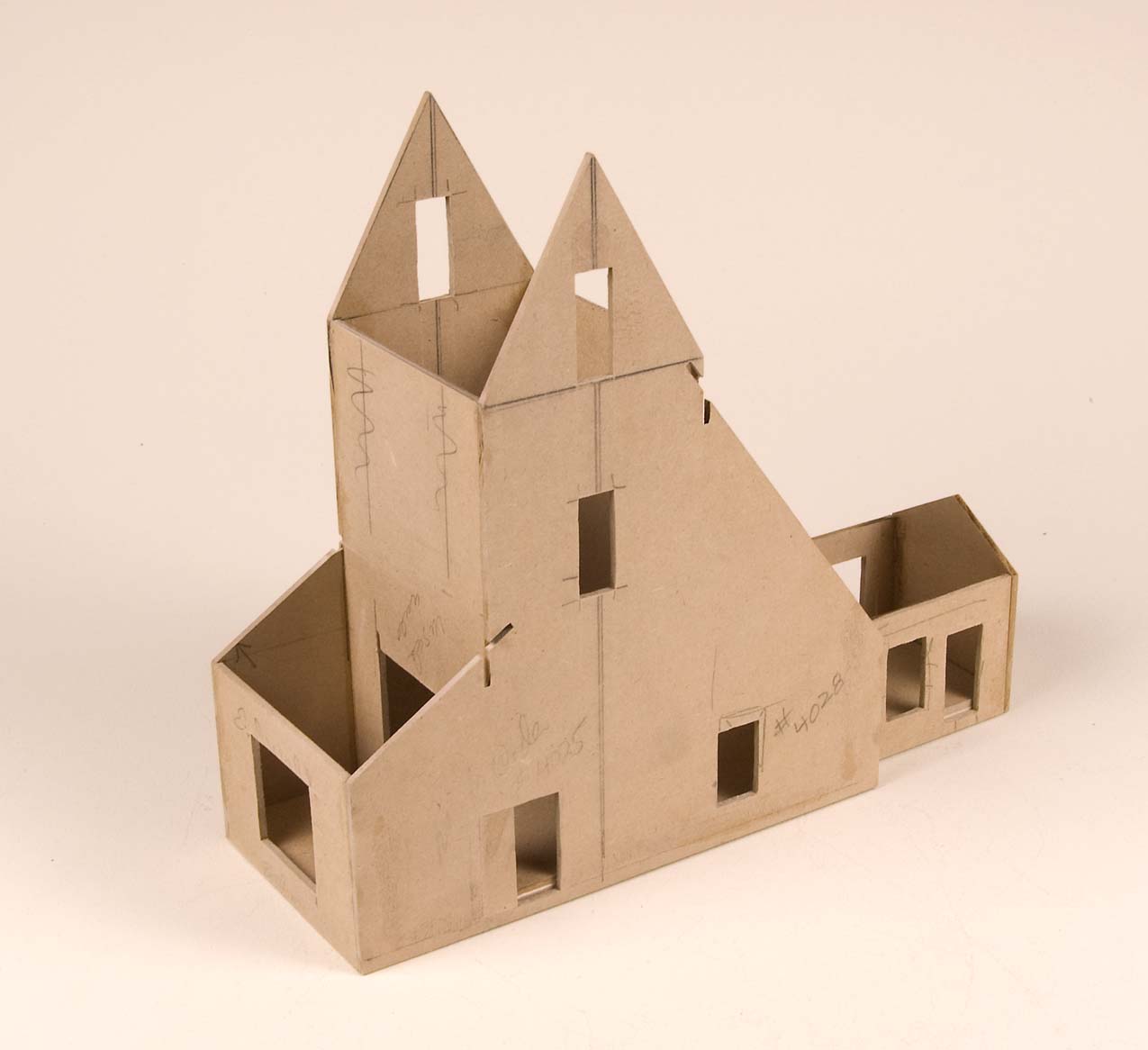 Photo 45 The various components were glued together with yellow carpenter's glue | 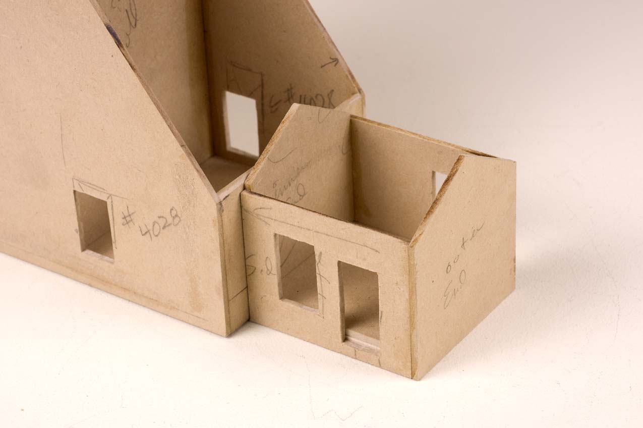 Photo 46 The small addition that serves as a small office was designed as a separate structure and glued at the rear of the larger mine unit. |
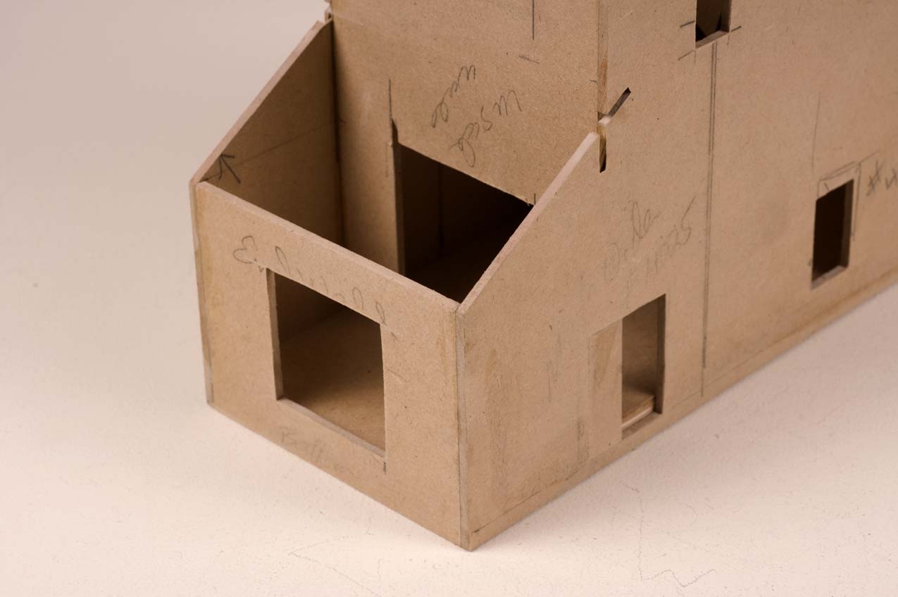 Photo 47 The opening in this part of the mine building will eventually be filled with the end of the conveyor structure that connects with the head house of the bunker. | 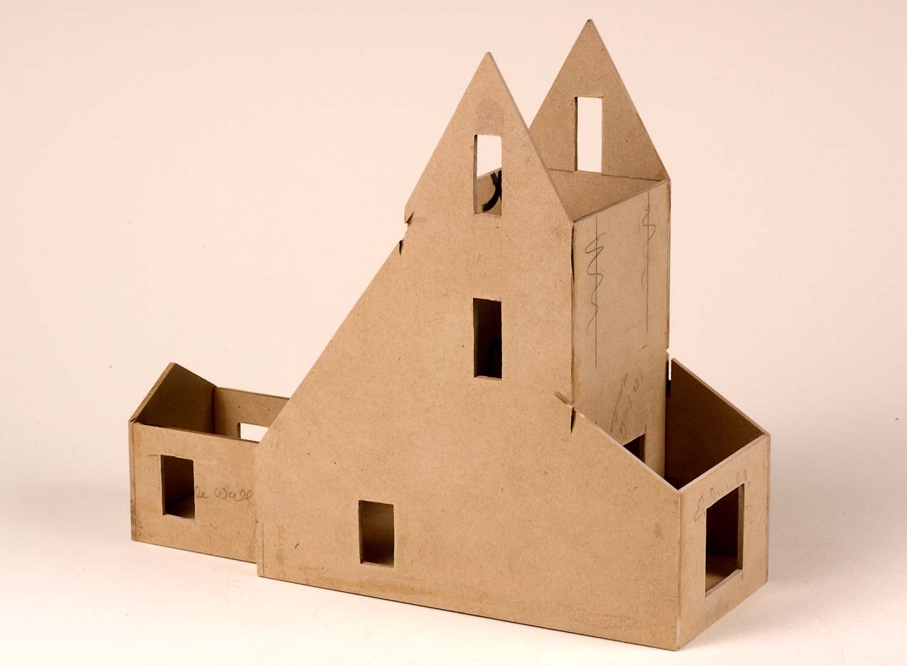 Photo 48 This is the side of the mine that would be slightly visible from the other side of the layout room. Since access to this side by miners would be difficult, no doors were needed on this side. |
 Photo 49 The thicker plywood piece will eventually be glued to the mine building supporting base and help with it's alignment. The thinner fiberboard piece will be glued to the interior walls of the mine and serve as its floor to add strength. | 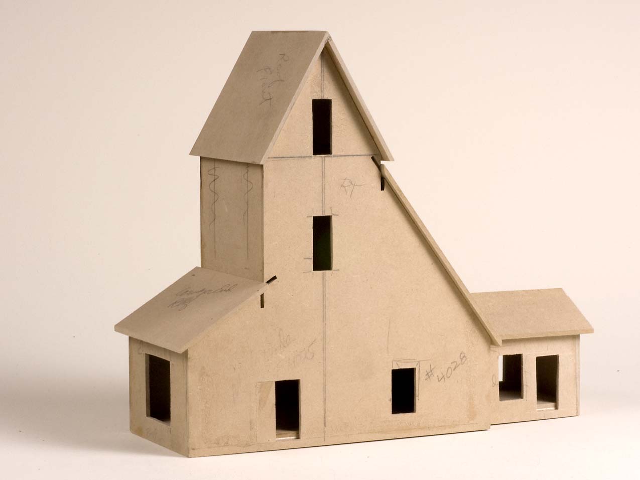 Photo 50 The roof components have been cut, fitted and set in place. The rear roof of the mine and the one for the small office addition were glued together and act as a single unit. The peaked roof of the mine and sloping roof over the front end are separate components. All the roofs are removable. |
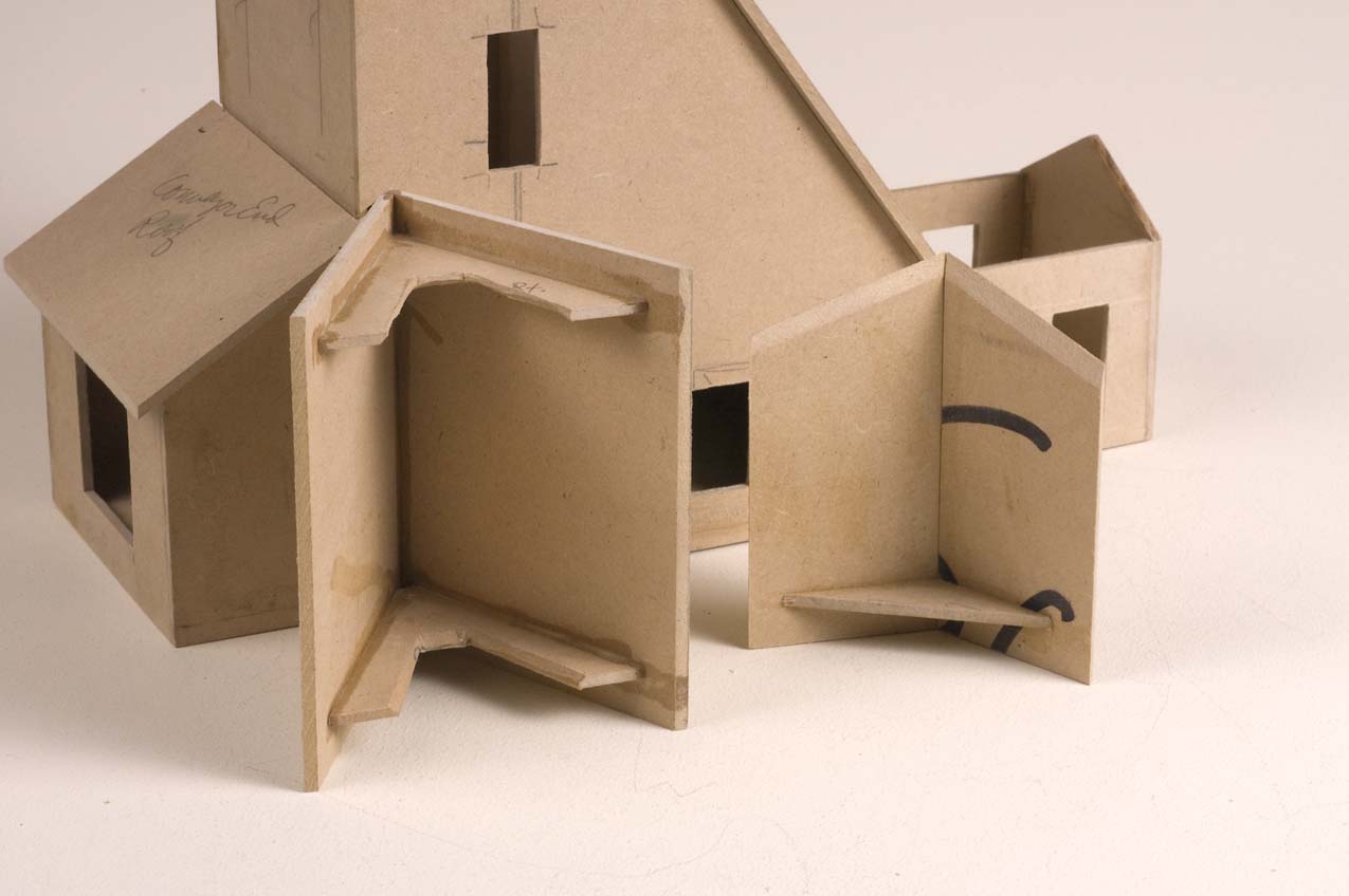 Photo 51 Here are the roof components for the mine and office addition. The office roof still needs to be glued to the rear mine roof panel. | 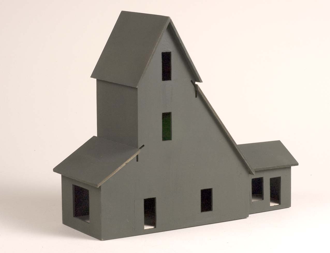 Photo 52 The mine structure would be covered with stripwood. To prevent the cream colored fiber board supporting structure from showing between the lengths of stripwood, the entire exterior was sprayed with Krylon, "Olive Green," flat finish camouflage paint. |
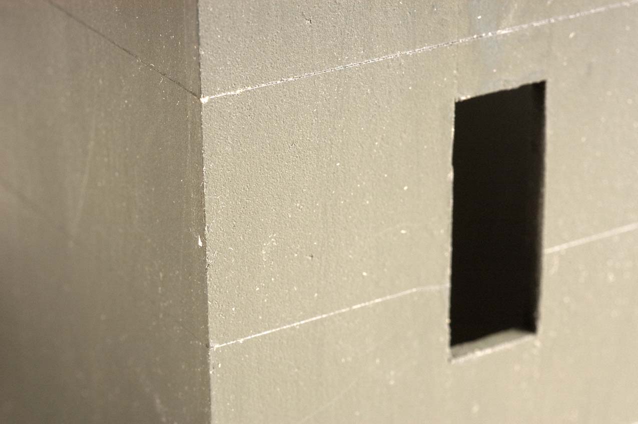 Photo 53 Guide lines were scribed onto the exterior walls at a scale 6' interval to aid in attaching the stripwood siding. | 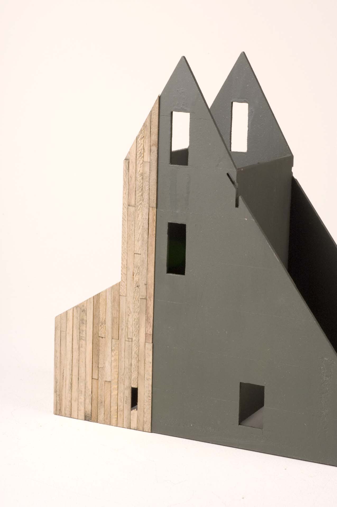 Photo 54 The application of the siding lumber has begun using Aleene's Tacky Glue to attach the stripwood. As before, the door and window openings were covered and the excess removed later when everything was firmly glued in place. |
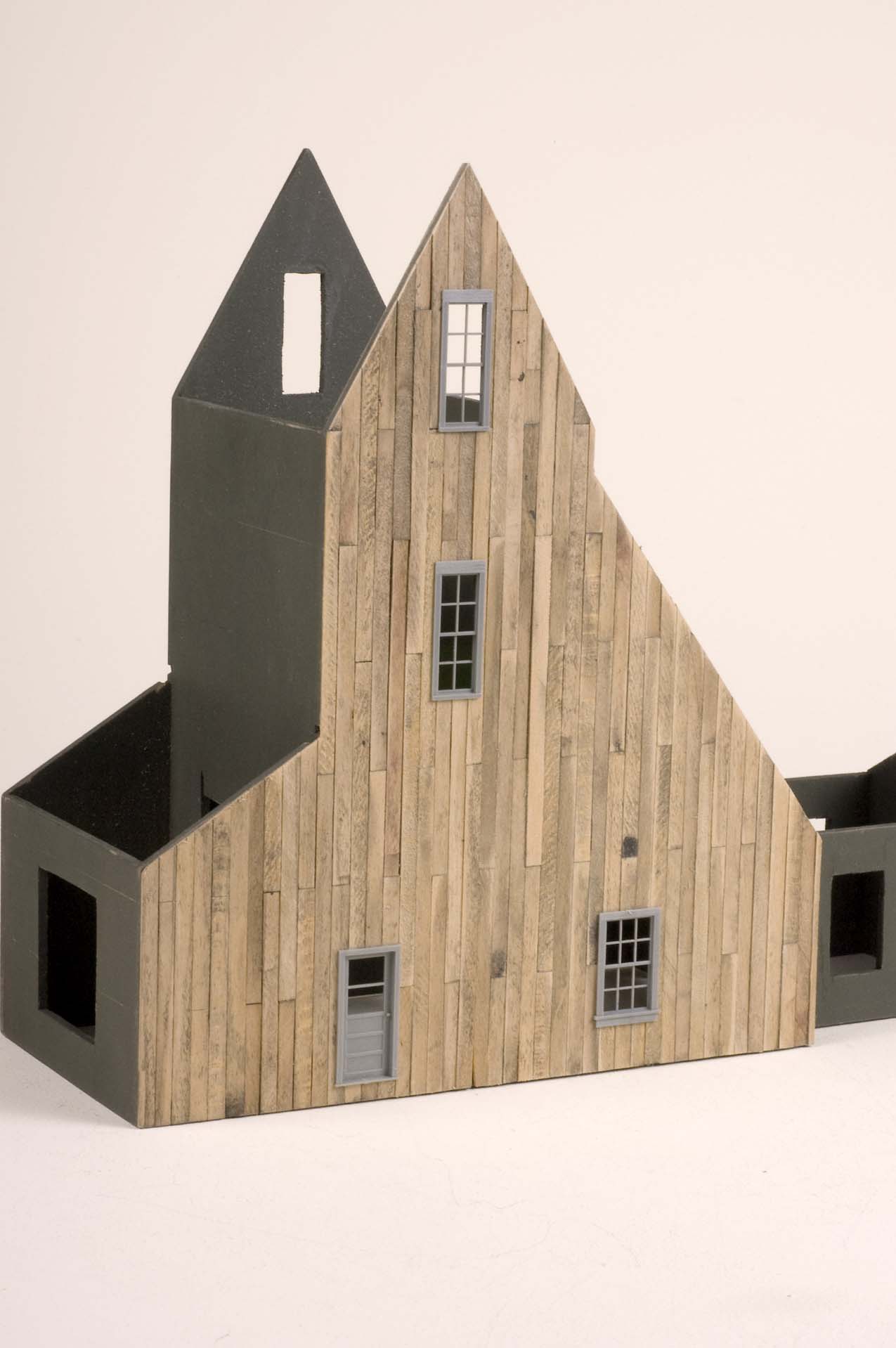 Photo 55 As soon as the door and window openings were cleared of excess stripwood, Grandt Line door and window castings were test fitted in place to see how they would look. | 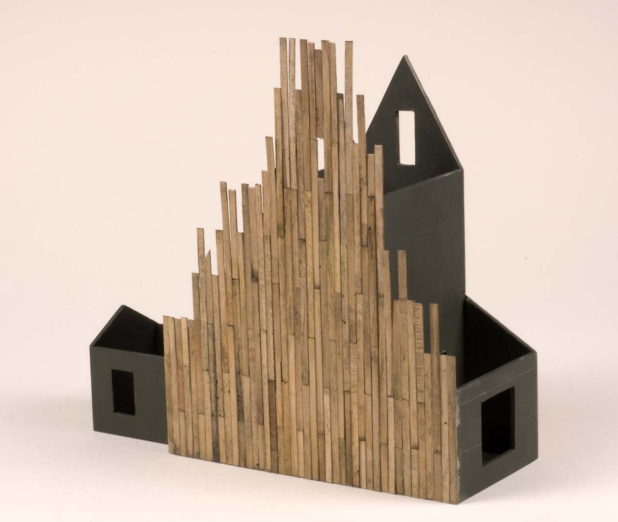 Photo 56 This view shows the left side of the mine building before the door openings were cleared of their excess material. |
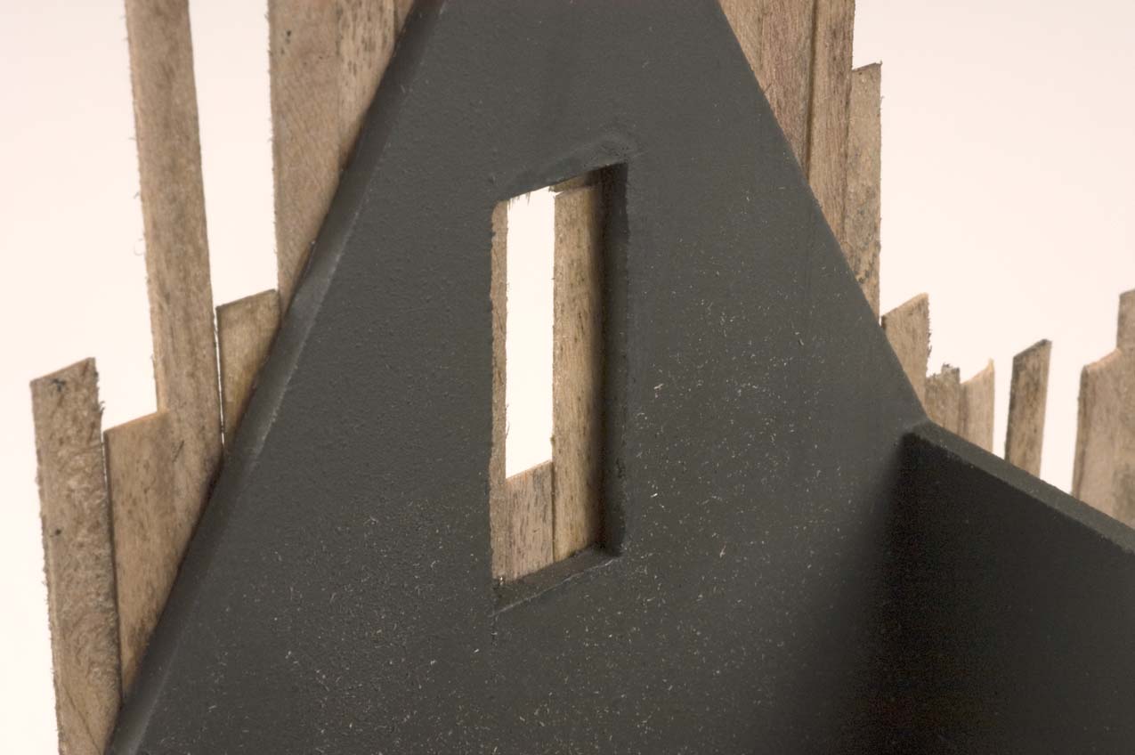 Photo 57 The stripwood still needs to be trimmed back to the edges of the building walls and also removed from the window openings. | 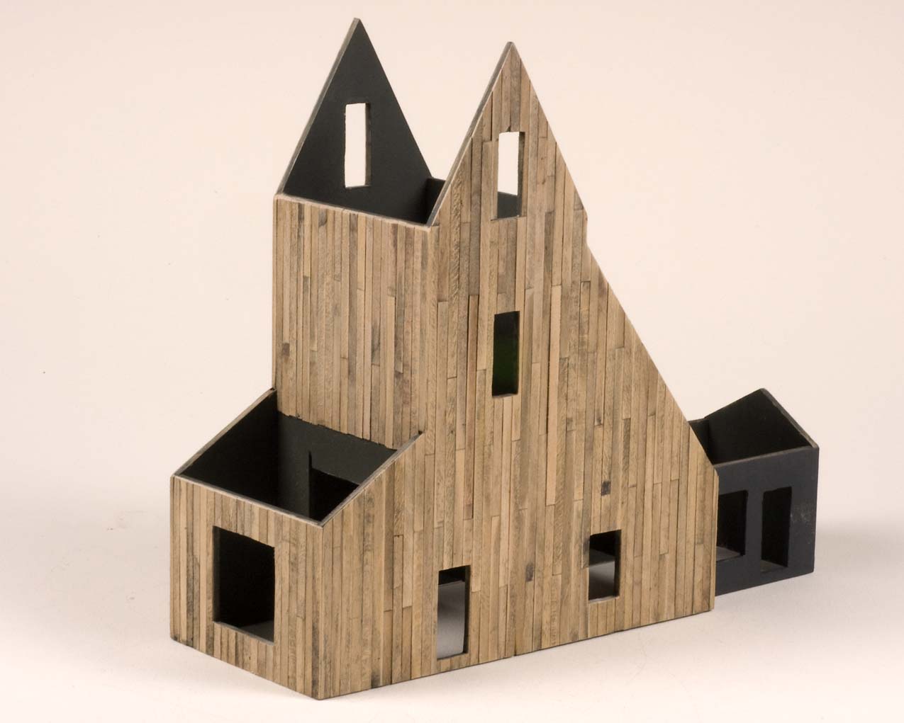 Photo 58 The application of the siding stripwood has been completed. The office addition will have tar paper siding and still needs to be covered. |
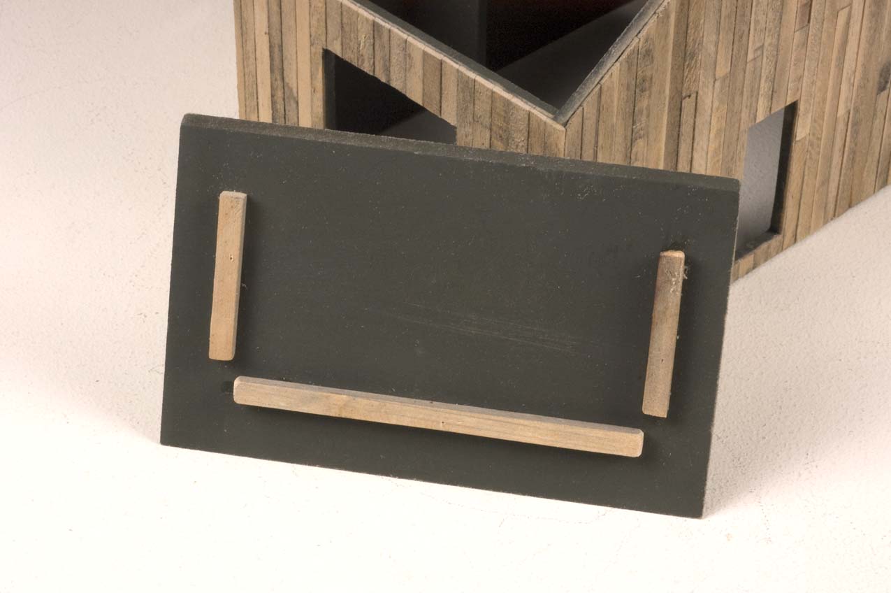 Photo 59 These three short pieces of stripwood were glued to the underside of the front sloping roof panel. They serve to locate and align the panel when it is placed onto the structure. | 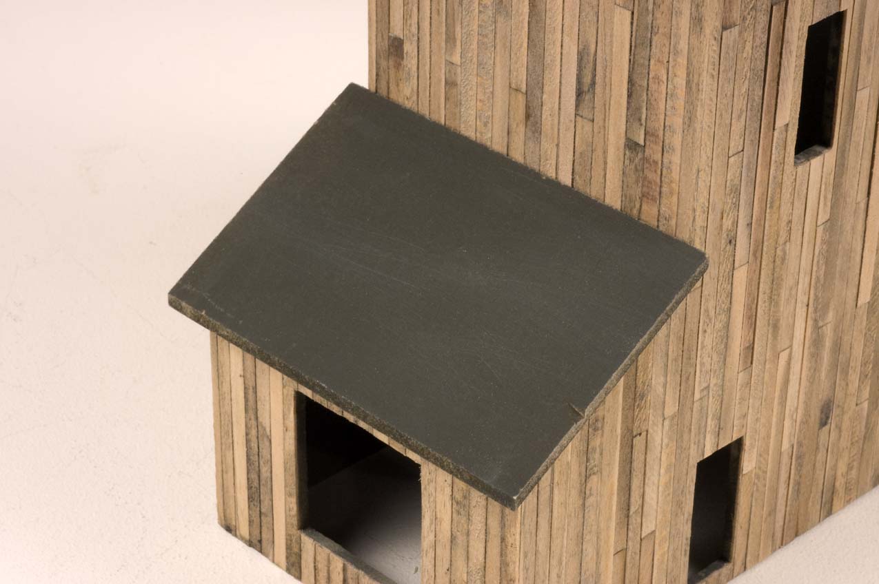 Photo 60 The previously placed pieces of stripwood make it easy to set this roof panel in place. |
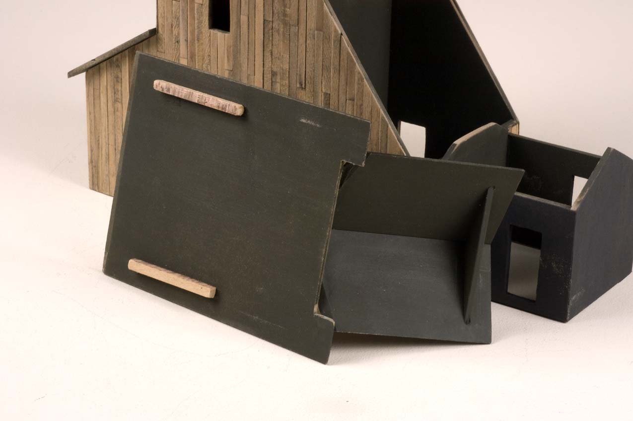 Photo 61 The office addition roof has been glued to the larger roof panel that covers the rear of the main mine structure. Two pieces of square stripwood on the mine roof and the angled former on the office roof help in positioning and aligning this component when it is set in place. | 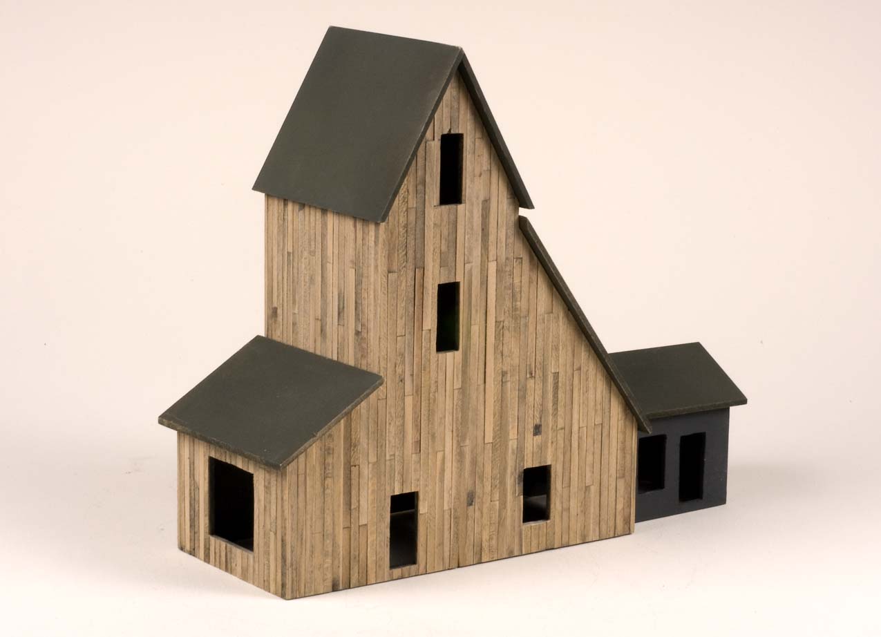 Photo 62 This view shows the mine structure with all roof panels set in place. |
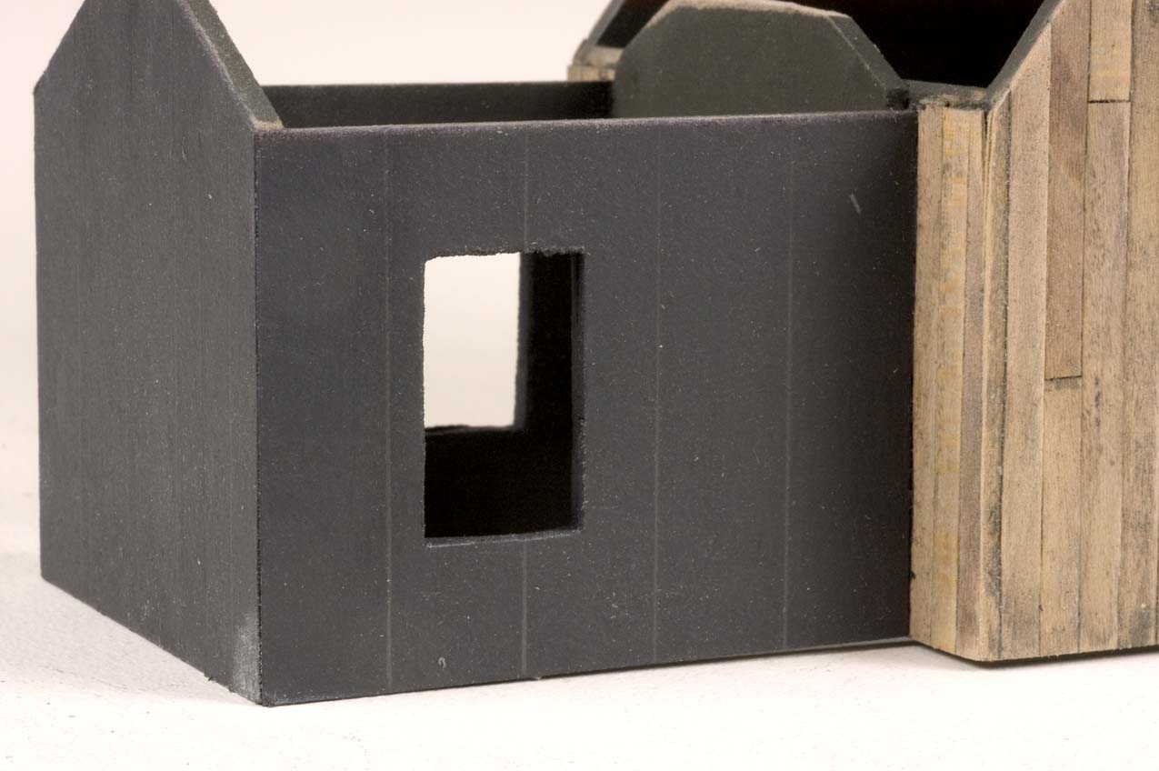 Photo 63 The exterior walls of the office addition were covered with the black craft paper. After the door and window openings were cleared, vertical lines were drawn at 3' intervals. | 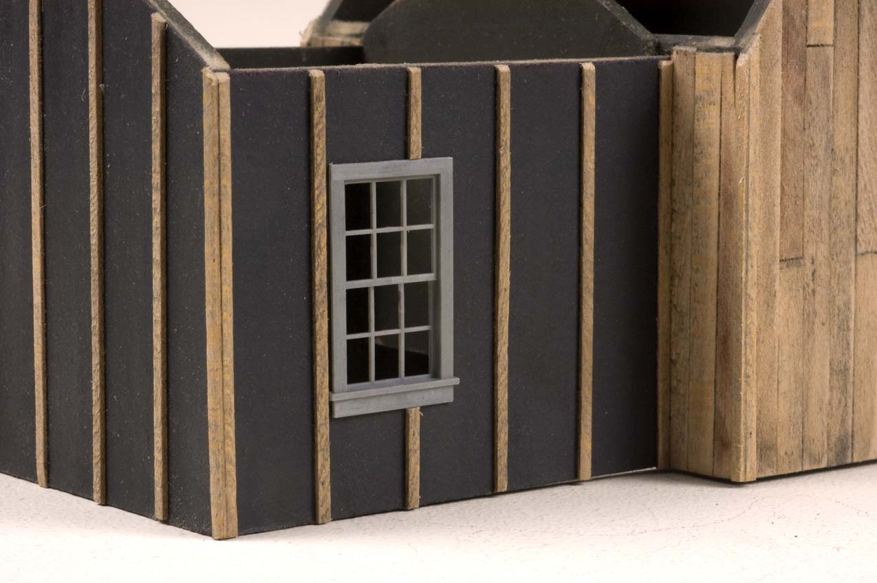 Photo 64 Thin batten strips were glued over the vertical lines and corner trim boards were added next. Grandt Line double hung window castings were test fitted into their openings. |
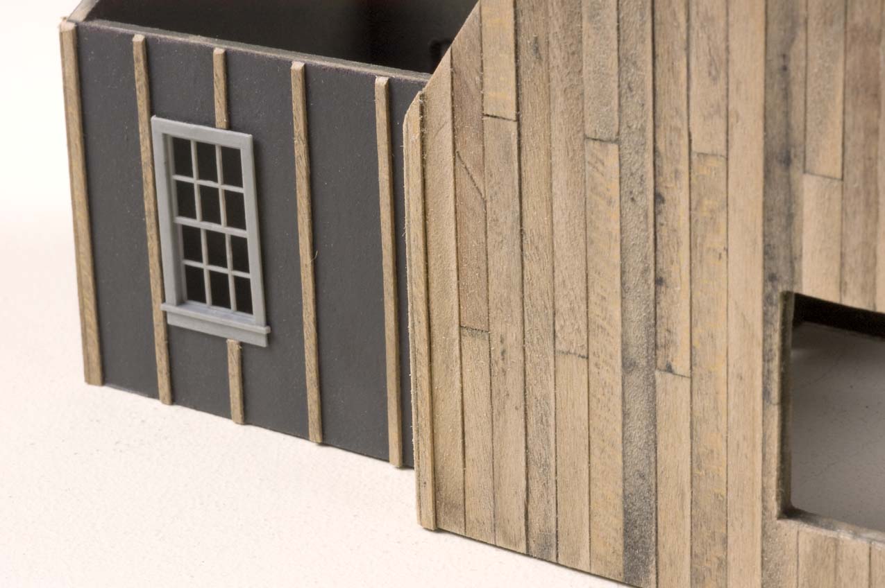 Photo 65 Corner trim boards were added to all the corners of the mine building and sanded at their top ends to match the angle wall line. | 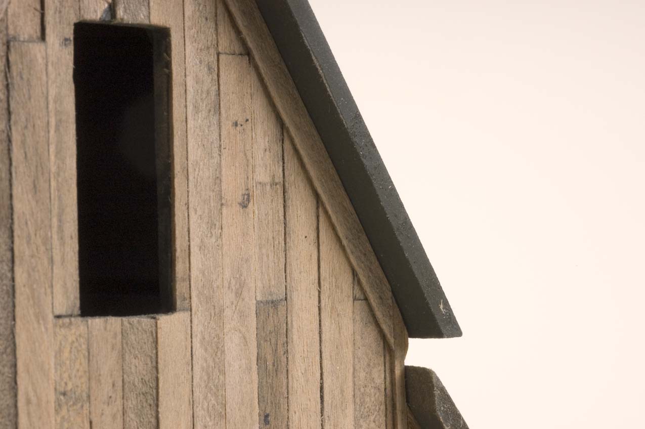 Photo 66 stripwood pieces were also added along the top angled edges of the side walls. The roof panel was put in place and used to obtain a tight fit. |
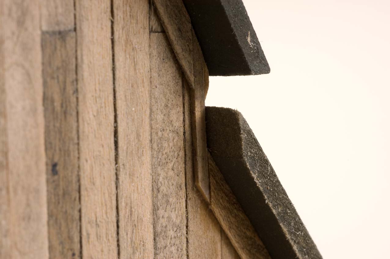 Photo 67 A small piece of wood was used to trim the short distance between these two top edge trim boards. | 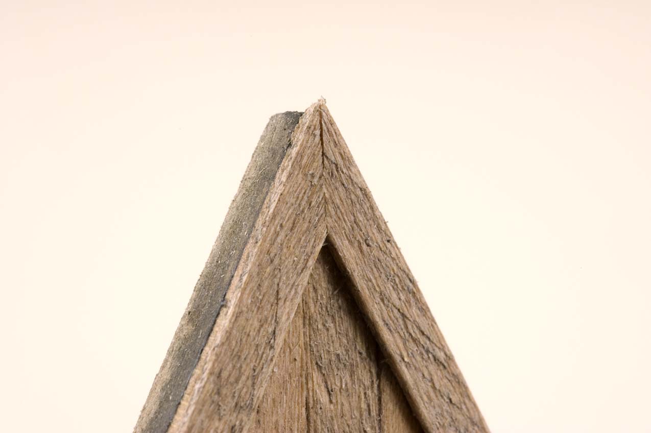 Photo 68 Careful cutting, sanding and trimming assured a tight fit of the side trim pieces at the top of the mine building. |
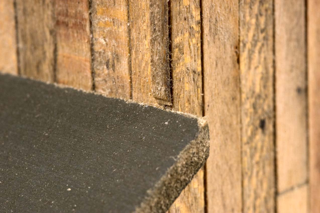 Photo 69 A small amount of the corner trim board needed to be removed to allow the sloping front roof to slip into place. | 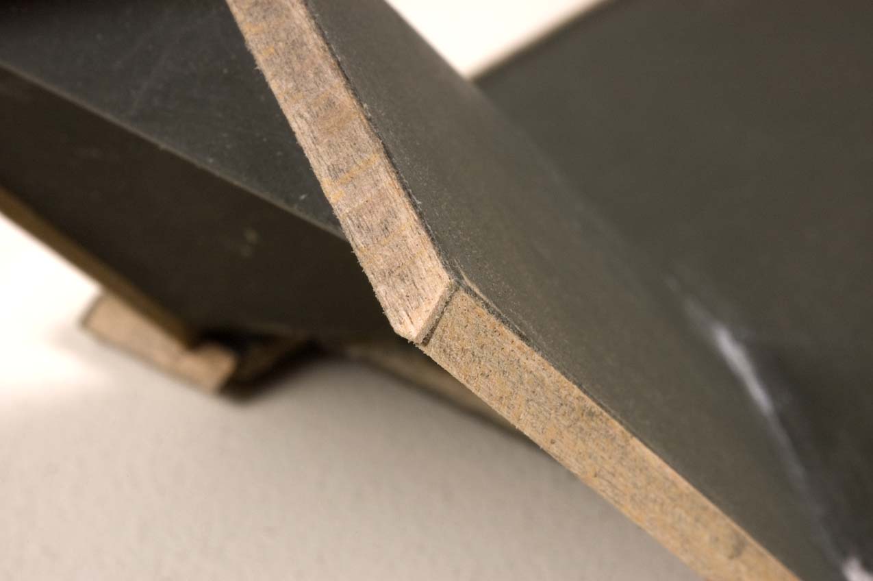 Photo 70 As was done on the ore house, stripwood pieces were attached to the edges of the mine roof pieces and sanded smooth and even with the outer surface. |
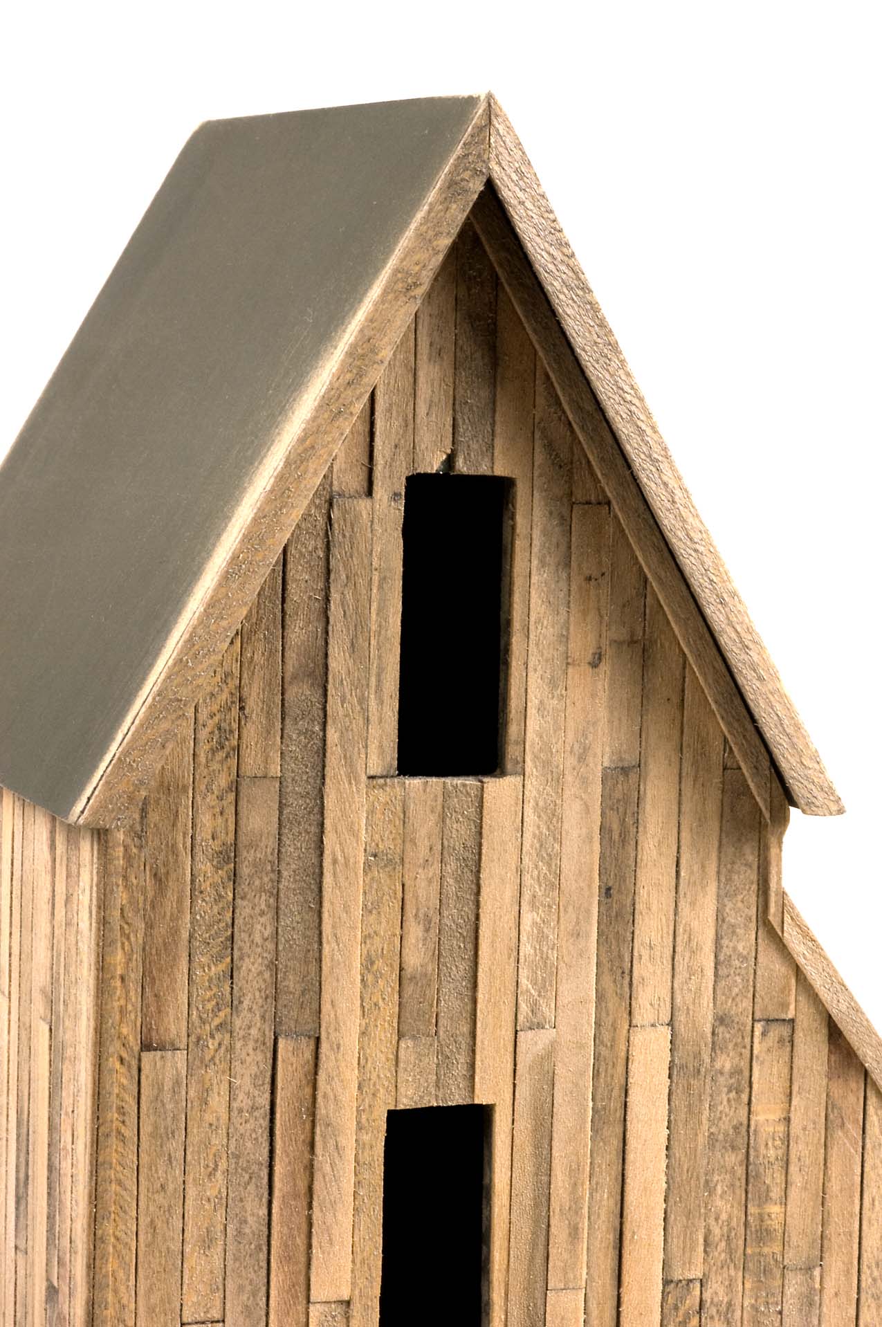 Photo 71 Pieces of stripwood were also cut, glued and trimmed to a point with a sanding stick to create a finished edge to the mine roof component. | 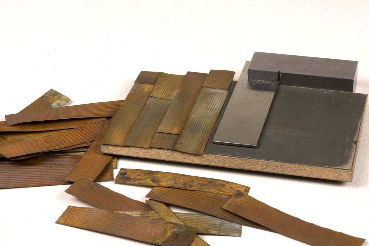 Photo 72 Strips of metal corrugated roofing material were trimmed to a scale 3' width, colored and weathered with Radio Shack Archer Etchant solution. Prior to placement on the roof, the pieces were given an additional dip in a very rusty looking, "Sweet & Sour," solution.When dry they were glued to the mine roof panels with Aleene's Tacky Glue. A random pattern was established to offer a realistic appearance. |
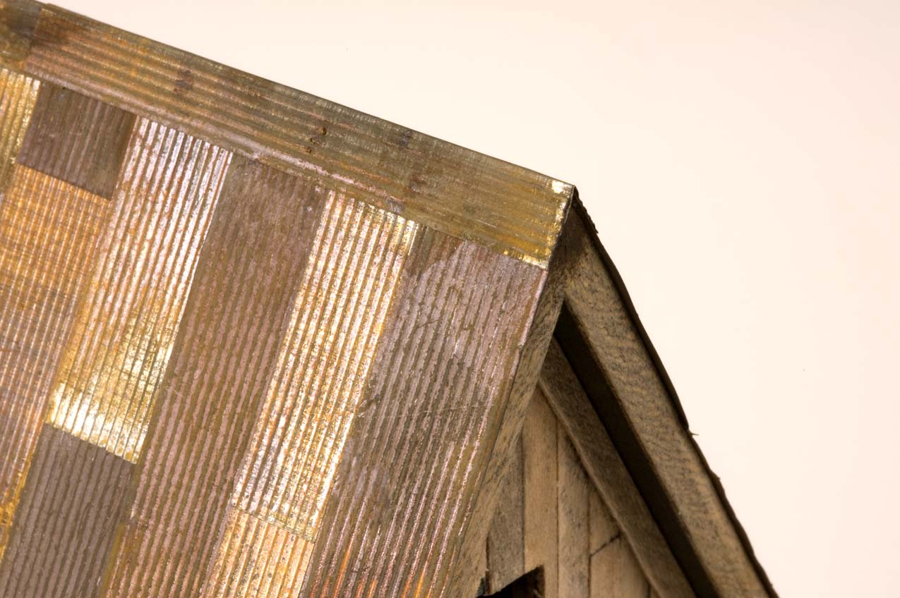 Photo 73 Once both faces of the roof were completed, a thin strip of the corrugated material was folded and attached along the top ridge, overlapping the others to deflect water. | 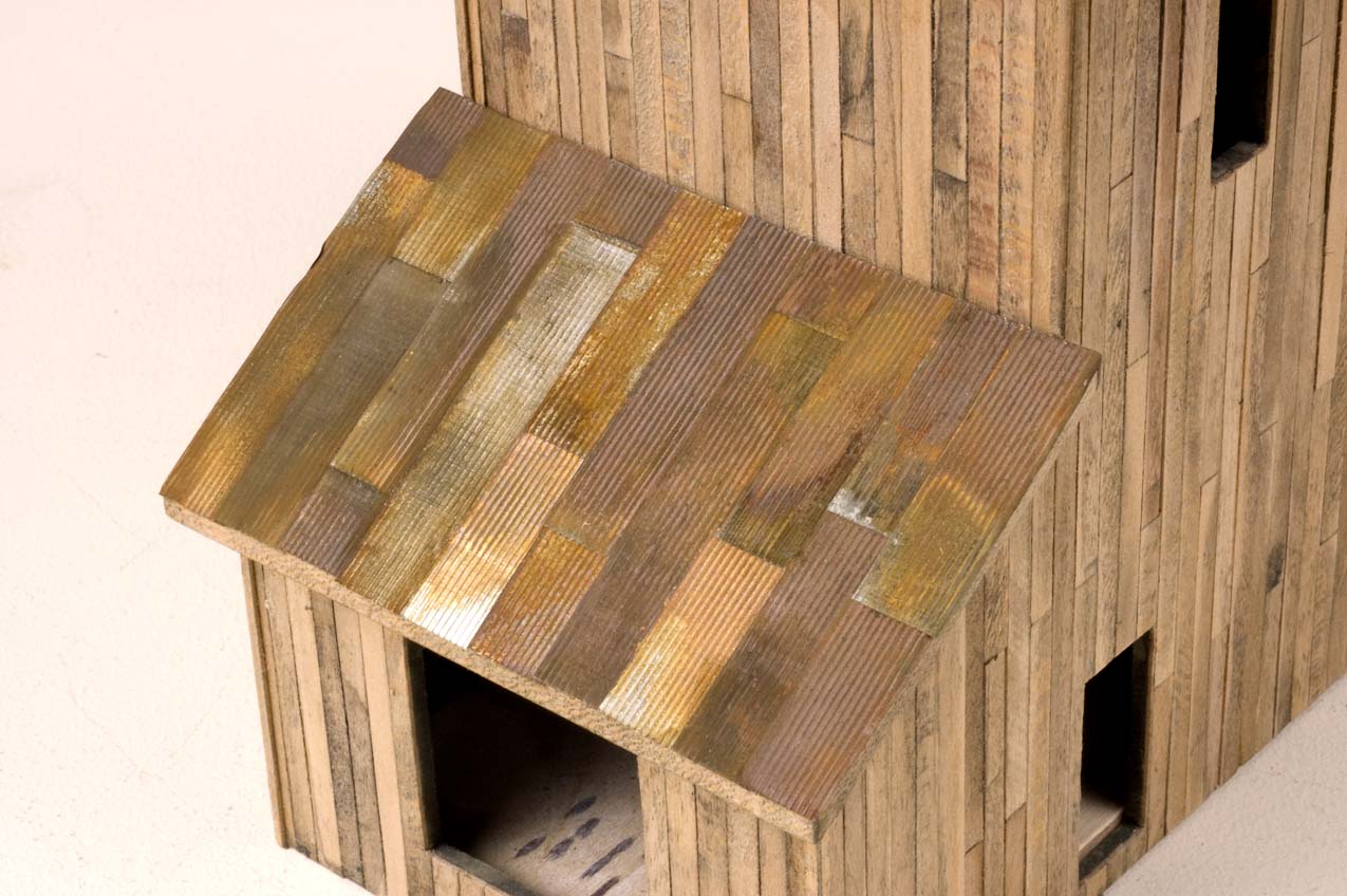 Photo 74 The metal roofing on this slopping roof illustrates the additional rust weathering created by the rust weathering solution. |
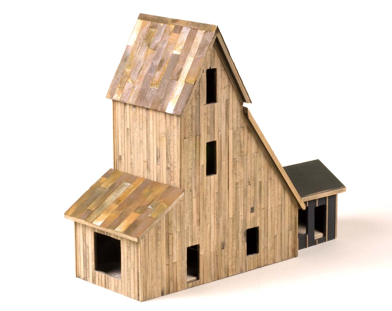 Photo 75 Once again, another photo was taken to show the building process. Windows and doors will be added next. | 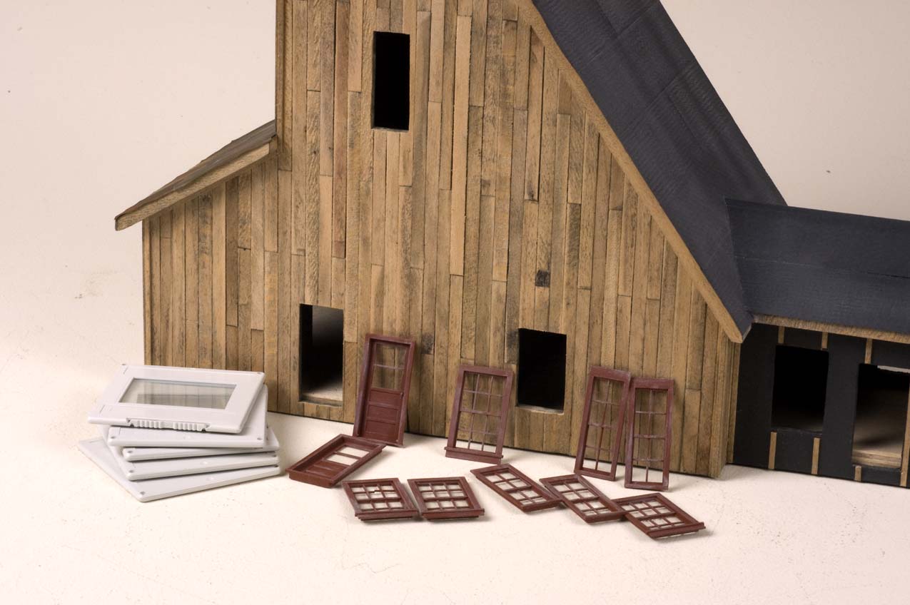 Photo 76 The Grandt Line castings were spray painted with Krylon, Ruddy Red primer and lightly dry brushed with white acrylic craft paint. Sitting next to the castings are a few of the 35mm slide mounts that provided the 1/32" glass for the window glazing. |
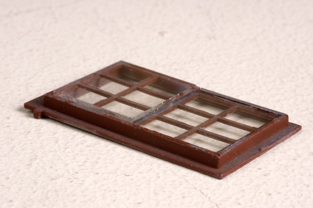 Photo 77 This view of one of the double hung windows castings has two pieces of the glass installed. They were held in place with a few drops of Dr. Mikes2 CA adhesive. | 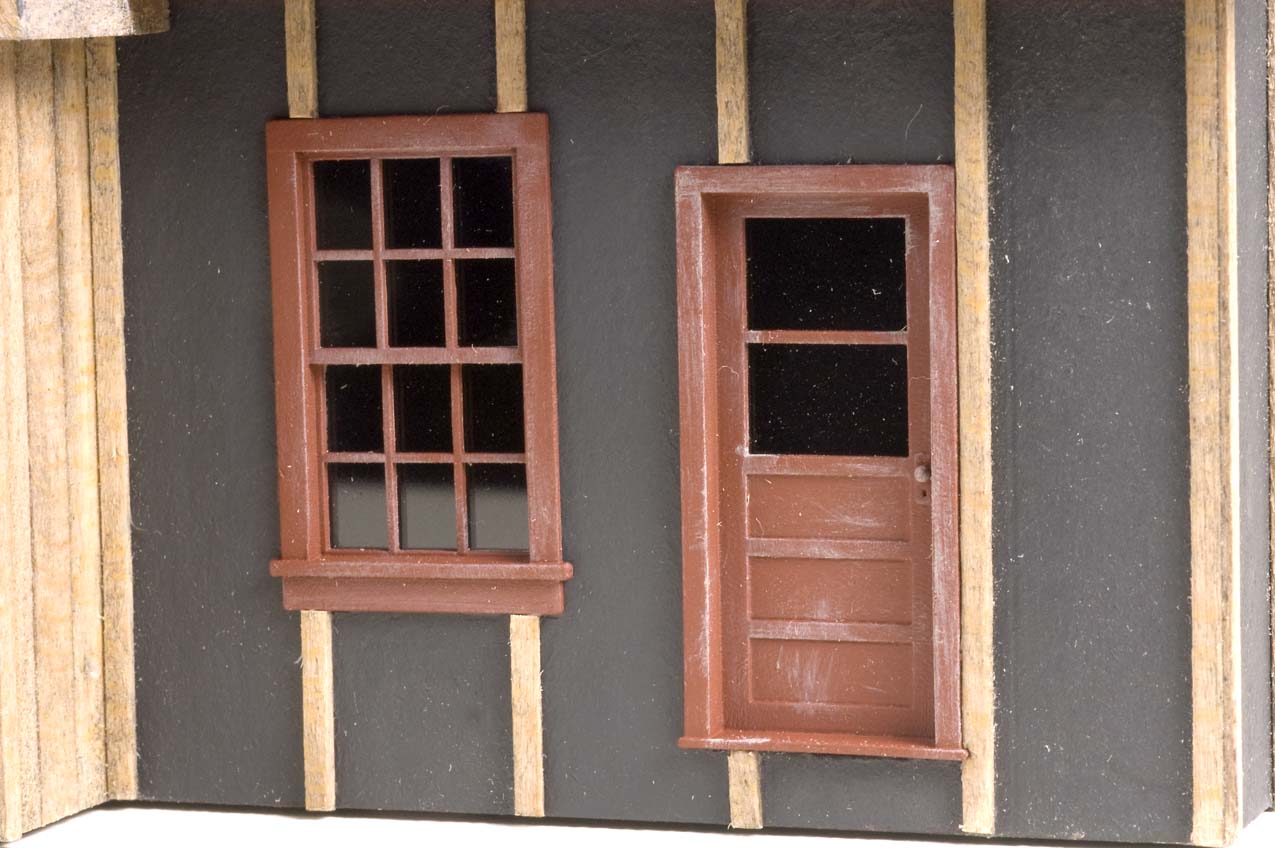 Photo 78 When ready, the door and window castings were glued into their respective openings with small dots of the tacky glue. |
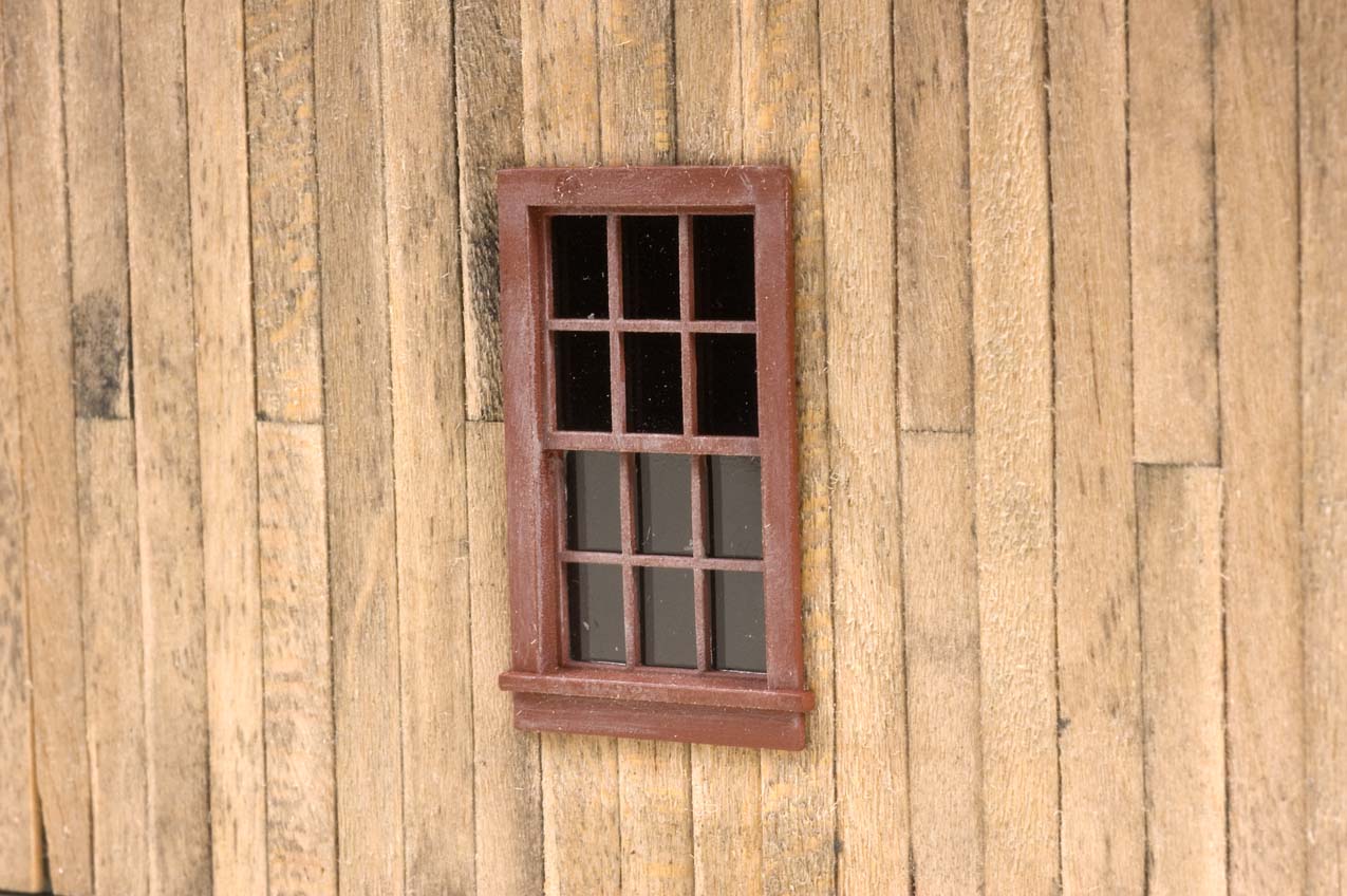 Photo 79 Here's another view of one of the window castings in the office addition. | 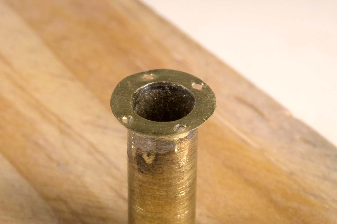 Photo 80 A short length of brass tubing, one size larger than what was used for the stack, was soldered to a piece of thin brass shim stock. When cool, the excess center material was trimmed away with a sharp hobby knife and its perimeter was cut into a circular shape forming a ring. Finally, four holes were drilled in the ring for the supporting lines. |
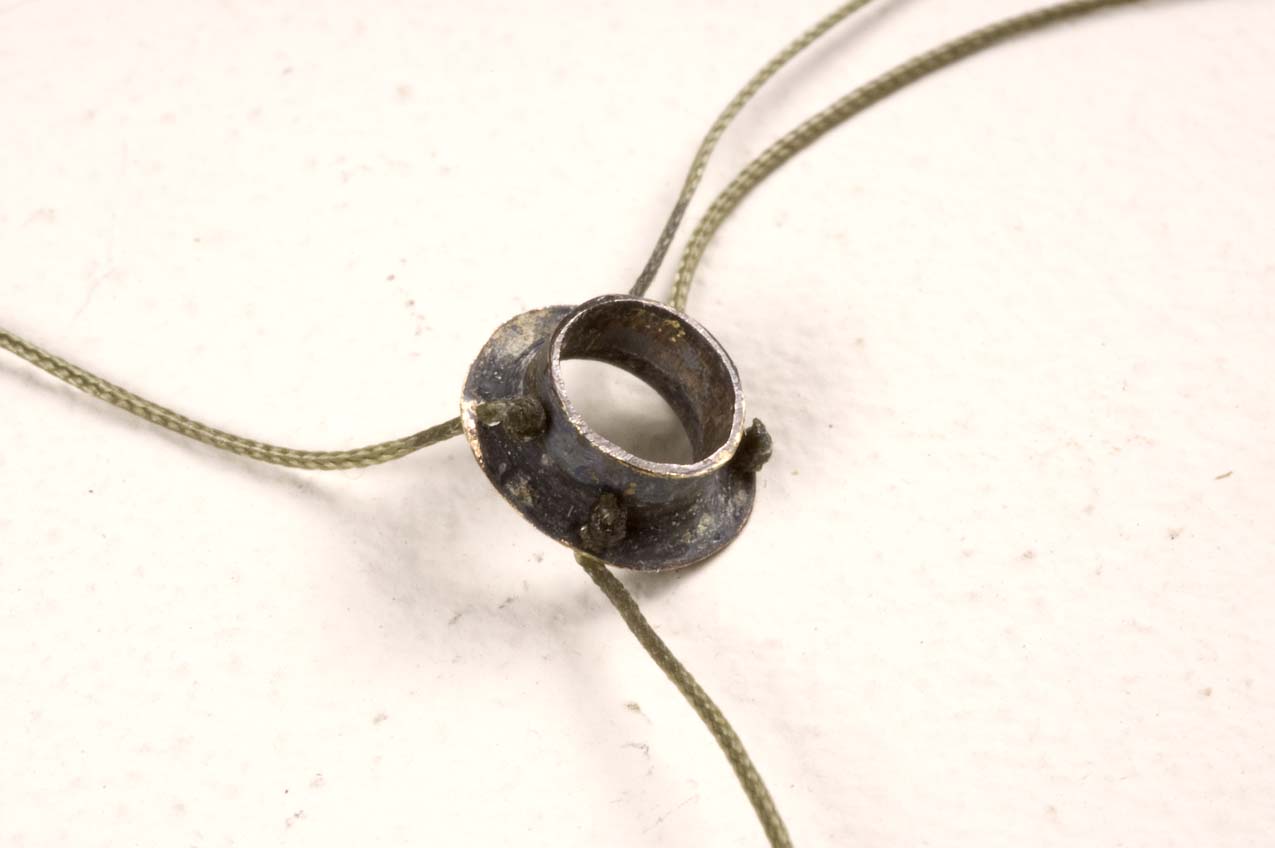 Photo 81 The ring, now looking like a mounting flange, was cut from the tubing and colored with the etching and gun bluing solution. Nylon fly fishing line was inserted through the holes and knotted. The knots were touched with a dot of the CA adhesive to secure them in place. Excess thread was trimmed with a sharp knife. | 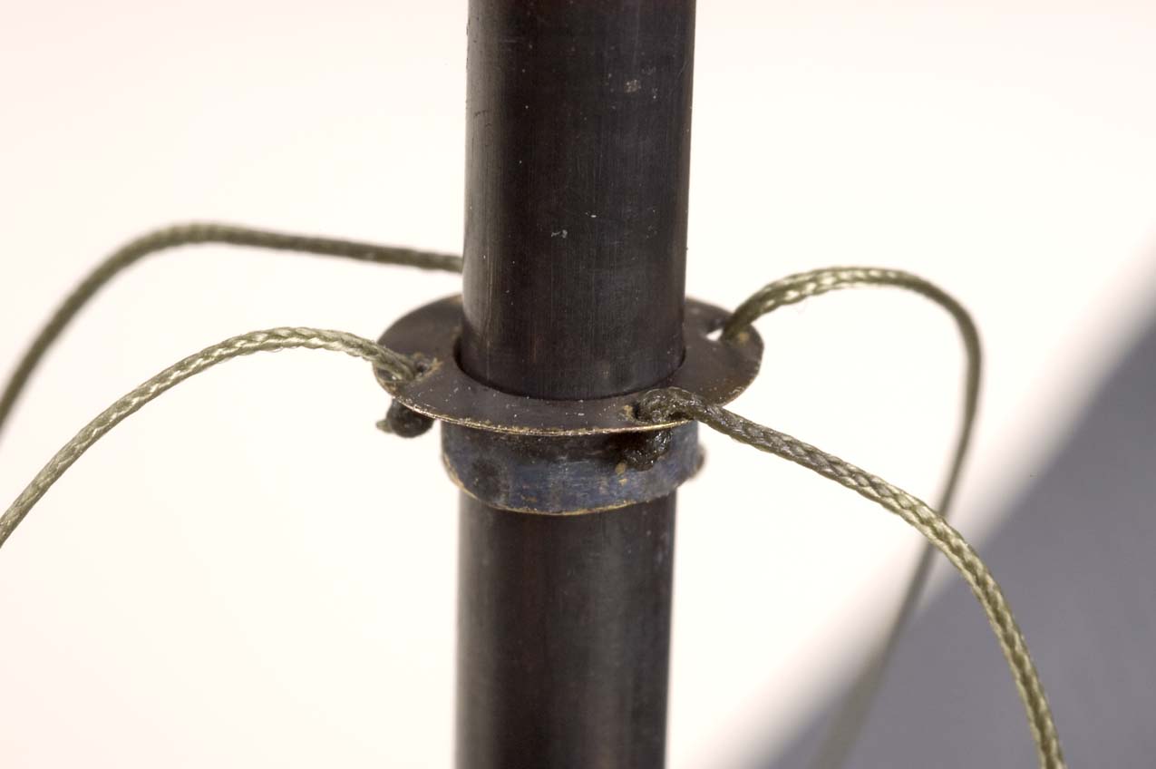 Photo 82 The mounting flange was slipped over the stack and glued in place with a dot of CA once it was positioned correctly. |
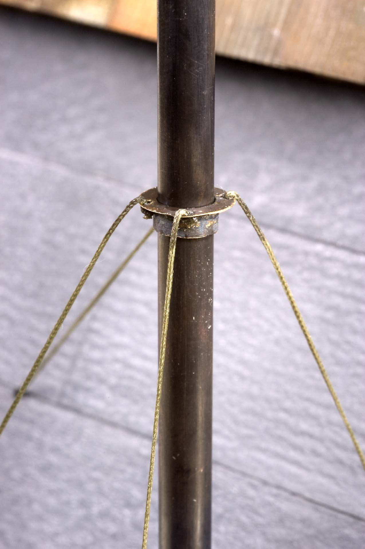 Photo 83 Here's another view of the mounting ring with the four guy lines secured in place. | 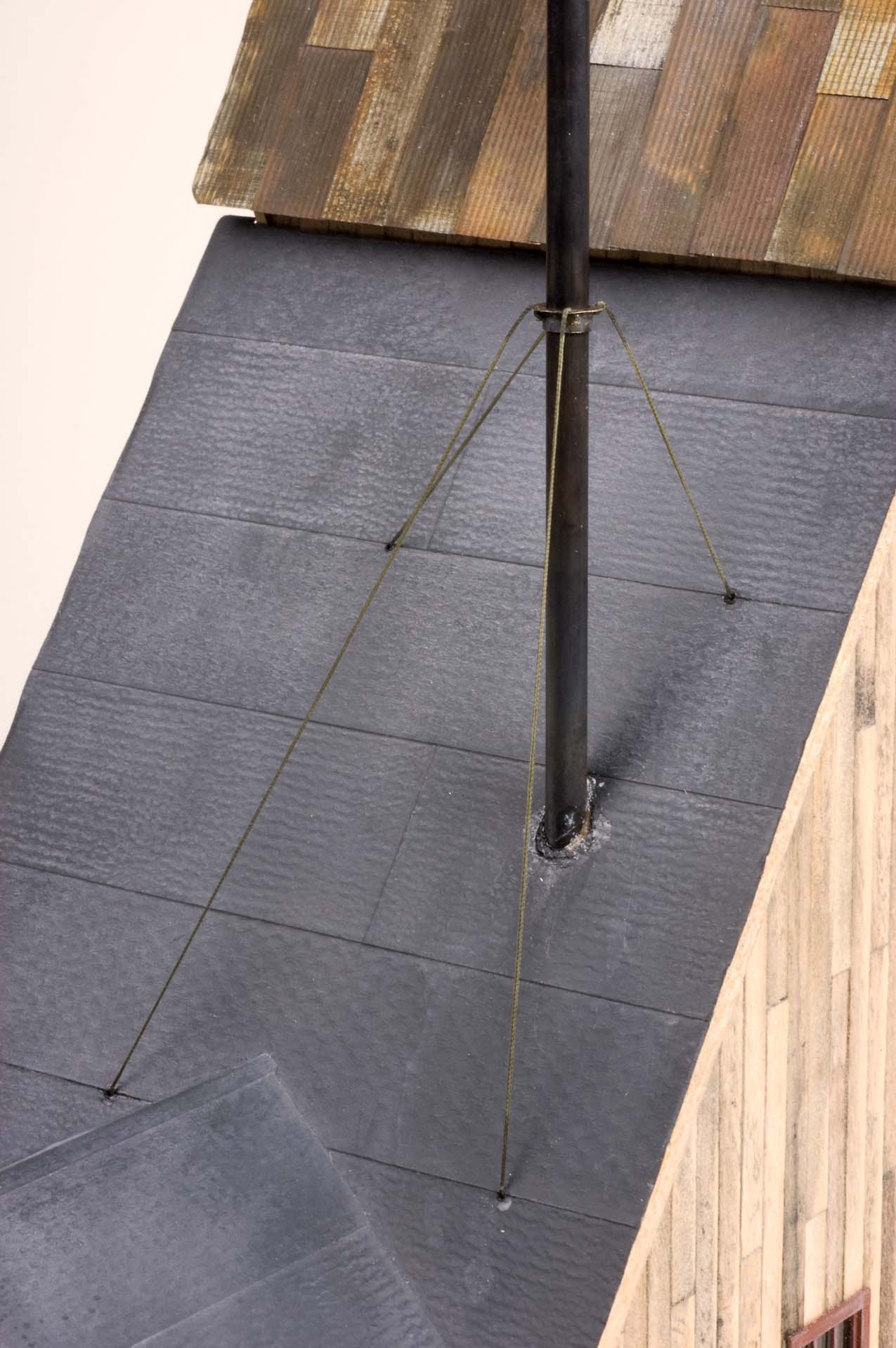 Photo 84 The four guy lines were routed through four holes drilled in the roof and secured in place with more of the CA adhesive, making sure the stack was vertical. |
 Photo 85 Additional weathering and rusting effects were achieved by adding a few drops of the rusting solution used on the corrugated roofing panels. It was applied to the mounting ring and allowed to run down the stack. | 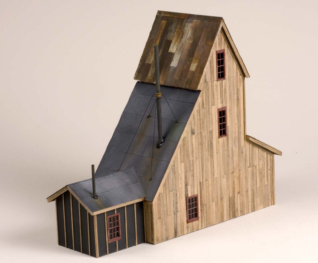 Photo 86 A shorter stack was installed through the roof of the office addition and secured in place with 5-minute epoxy. Besides using CA to initially hold the brass tubing in place, 5-Minute epoxy was also applied around the underside of the roof to reinforce their bonds. Additional epoxy was also applied around the roof where the stacks were mounted. It was them painted glossy black to suggest roofing tar. |
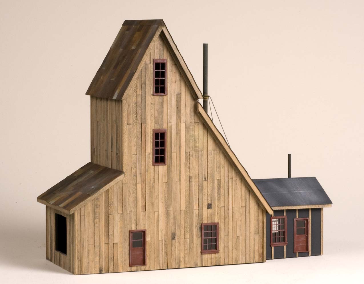 Photo 87 This view shows the mounted smoke stacks with the almost completed mine building. | 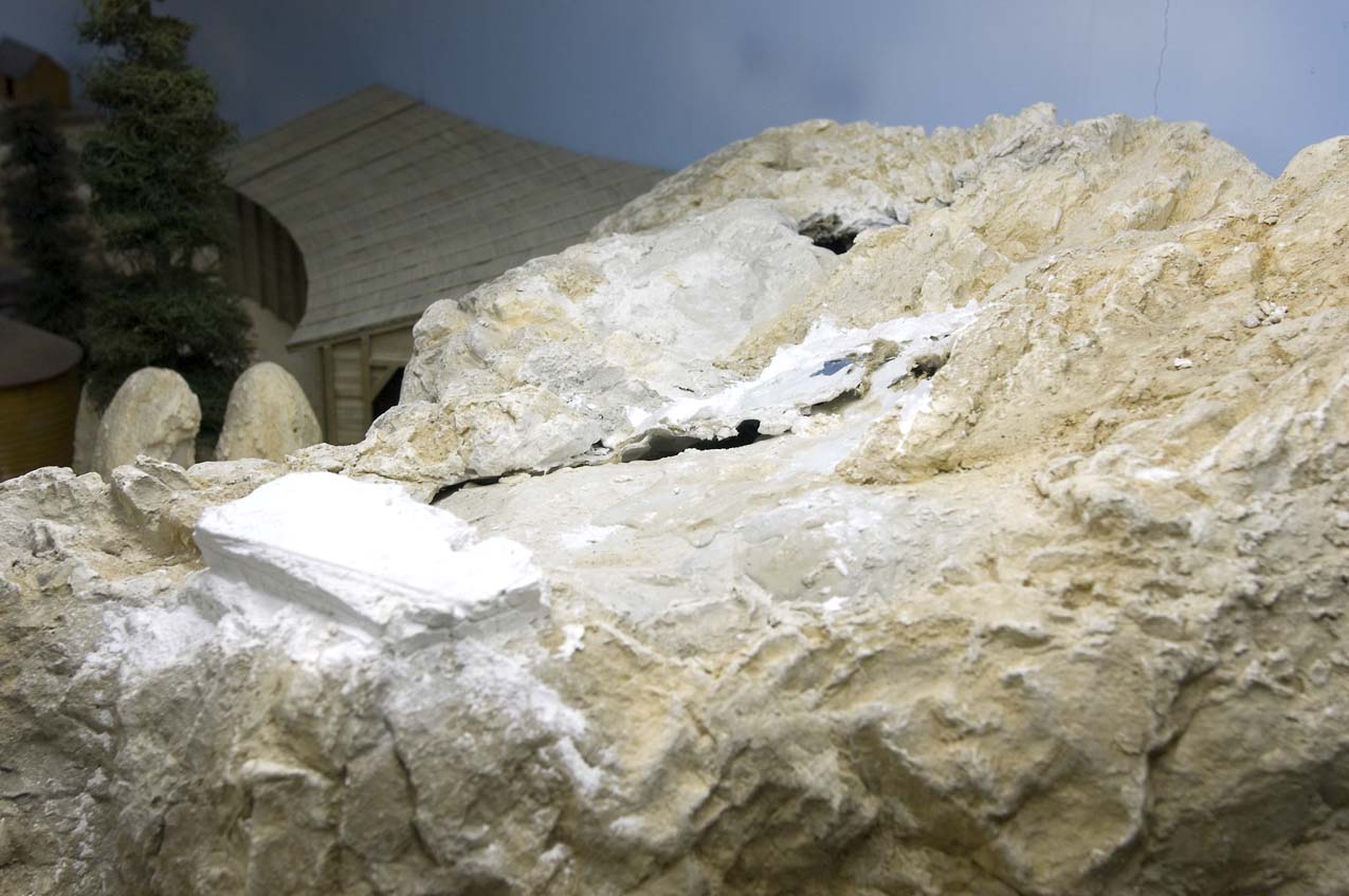 Photo 88 Here is a view of the mine site at the top of the mountain. Some plaster rock work has been started but a level surface for the mine building needs to be created next. |
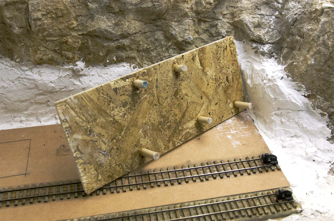 Photo 89 To create a flat site for the mine atop a mountain, I needed something that I could set into the existing terrain. A piece of 1/4” thick OSB material that was slightly larger than the footprint of the mine building was cut and drilled for a few pieces of wooden dowels. | 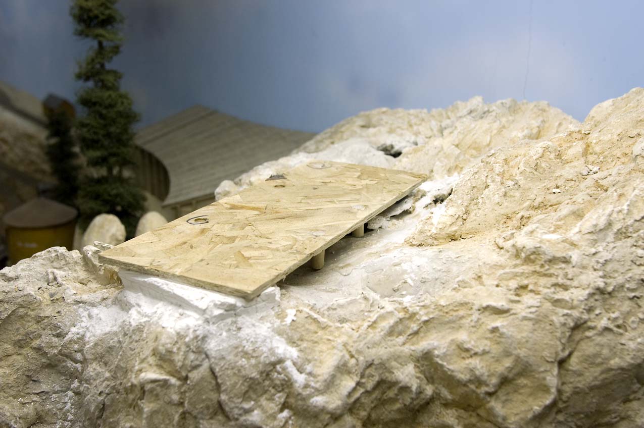 Photo 90 The OSB board was placed in position and leveled with a short torpedo level. When correctly adjusted, the dowels were pressed down until they touched the plaster hill side and glued tight so they couldn’t move. |
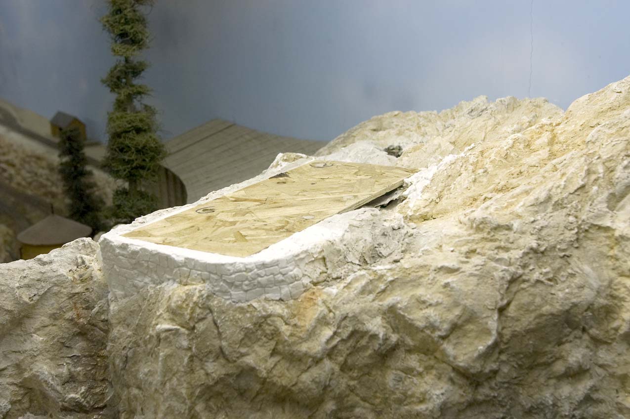 Photo 91 The edges of the OSB board were covered with clear packing tape and placed back into place. Plaster was then applied completely around it at all edges that would be visible while viewing the layout while standing on the floor. The plaster was leveled out to be even with the board. | 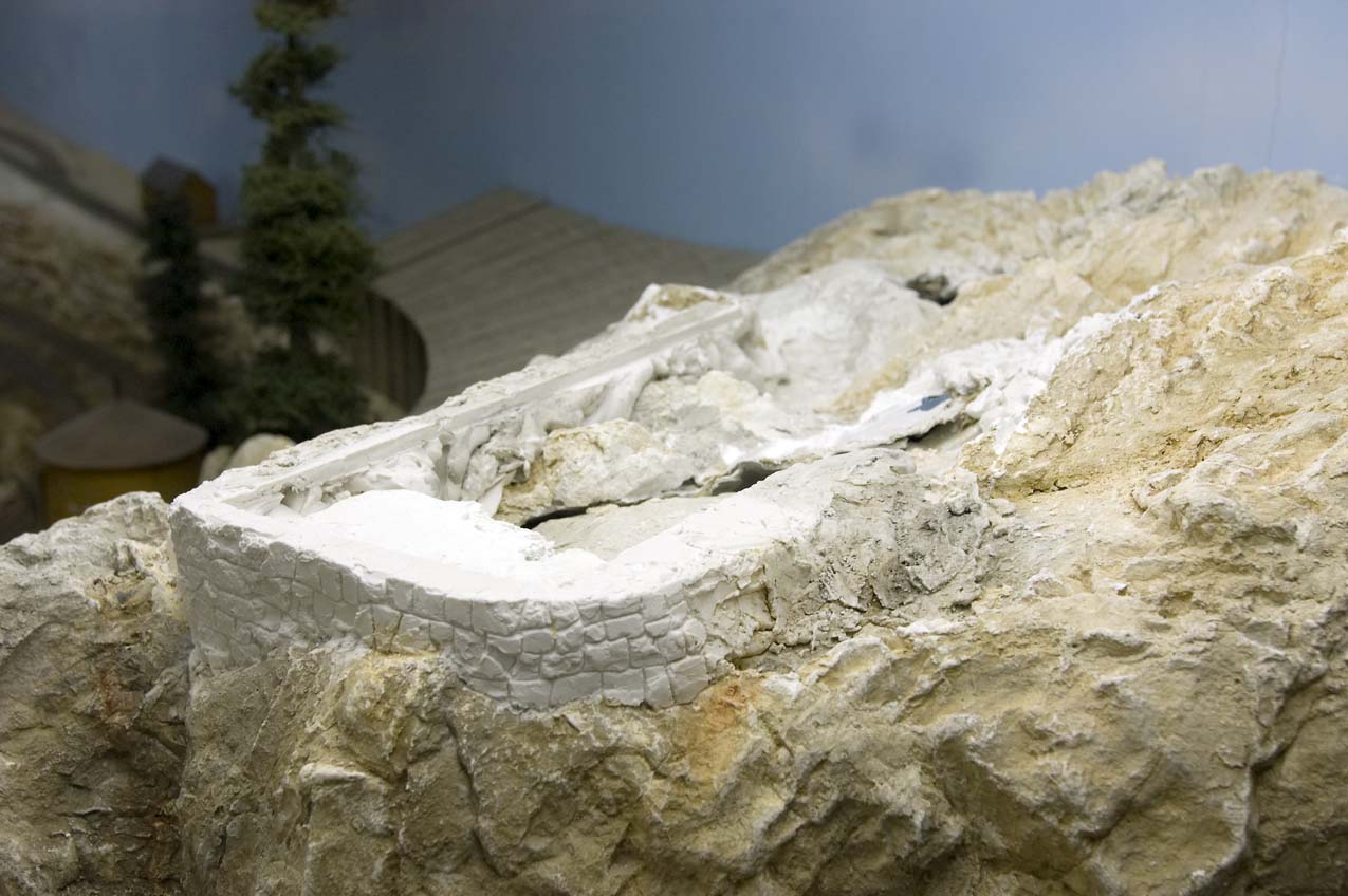 Photo 92 This view shows the area with the OSB base removed. Various dental tools were used to carve a stacked stone supporting wall effect. |
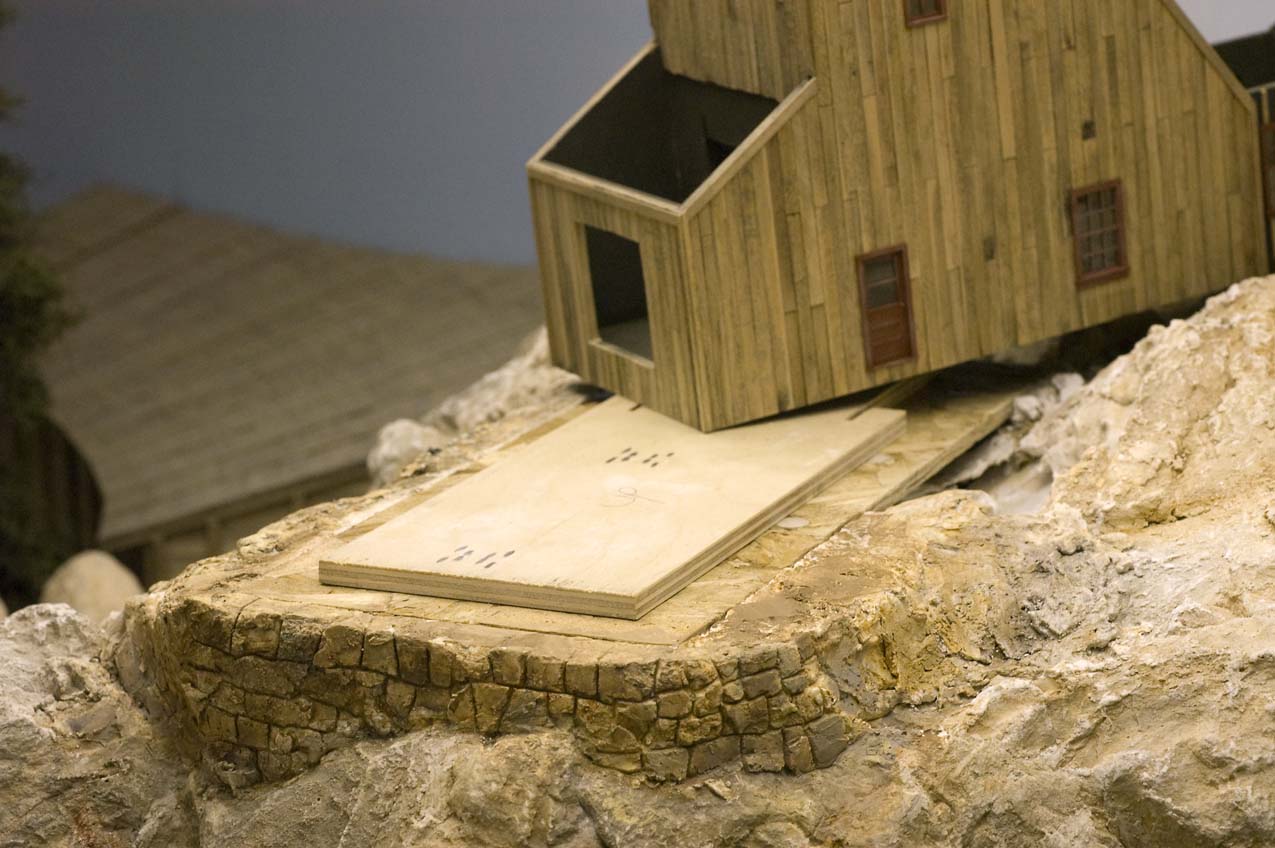 Photo 93 The 1/4" thick plywood alignment piece has been glued to the OSB board in a predetermined location. Note that the carved stone wall has been colored with washes of acrylic craft paints to match the surrounding scenery. | 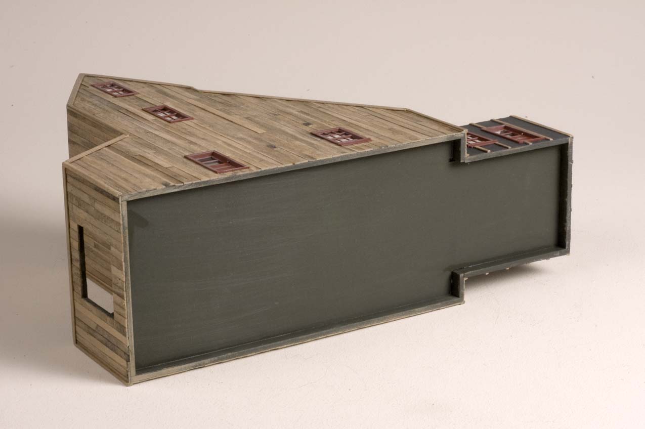 Photo 94 This underside view of the mine structure shows the fiber board floor glued in place. Note that it's recessed a bit to allow it to settle around and over the OSB alignment board that's glued to the base support. |
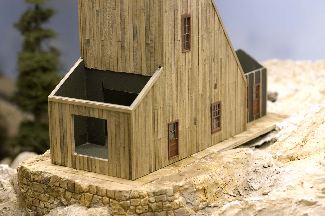 Photo 95 The mine building can be removed easily and reset back in place because of the alignment board. The ground around the base of the mine will not be sceniced because it can't be seen while viewing the scene while standing on the floor. | 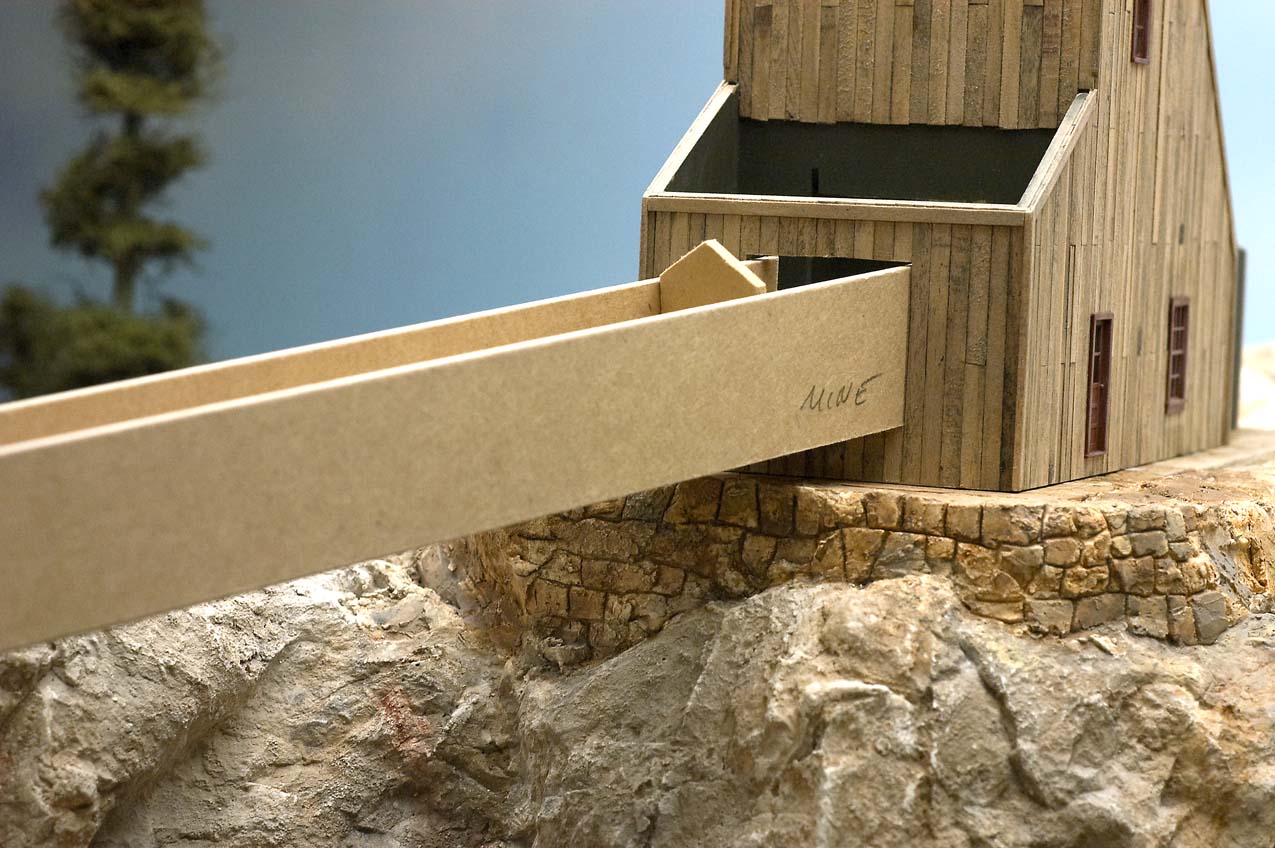 Photo 96 The connecting unit that would house the conveyor between the mine and the bunker head house was temporarily taped together and test fitted in place to see how it aligned with the mine building. |
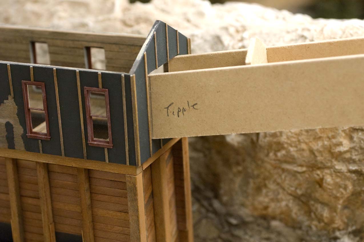 Photo 97 A little bit of sanding was necessary for it to fit in the head house. | 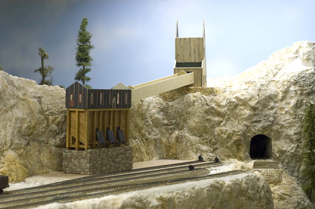 Photo 98 This view shows the overall scene of how the two main components of the mine complex will appear. Unfortunately, I didn't photograph the process of marking the five window locations in the wall panels. A large drafting triangle was used to make sure the ends of the windows would be horizontal. When marked, the window openings were cut out with the same right angle chisel and drill press that was used on the other window and door openings in the model. |
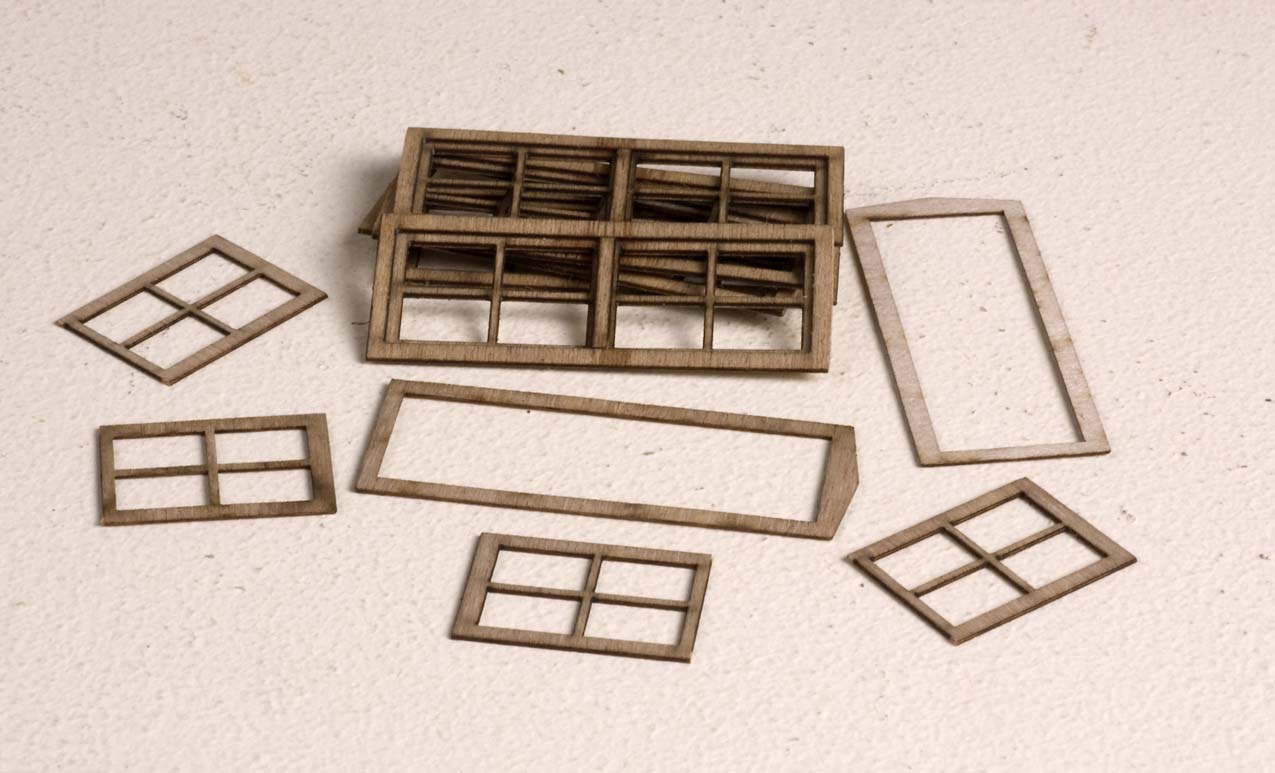 Photo 99 Double wide window components were fabricated out of laser cut double hung window pieces. The peaked end of the outer frame had to be removed for it to serve as a frame for the newly designed windows. | 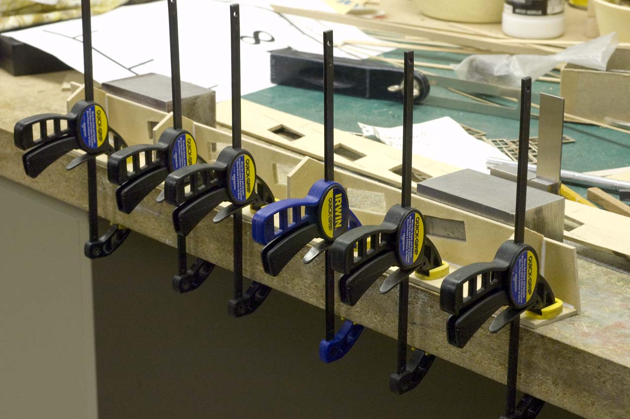 Photo 100 Now that the window openings have been cut out, the wall panels were taken to the work bench and fastened to the front edge with plenty of clamps. Four wall dividers and supports were glued in place at pre-determined locations. |
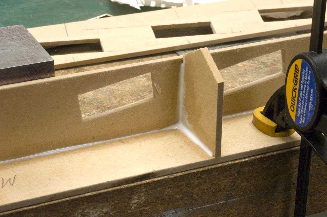 Photo 101 This is one case where I wasn't too careful about spreading glue because it would never be seen and I wanted the joints to be strong. | 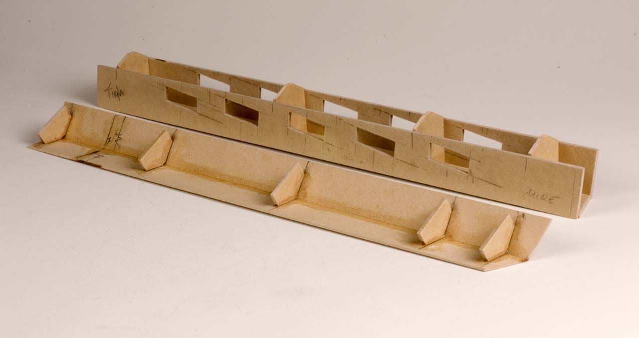 Photo 102 The two roof pieces were cut and test fitted in place between the mine and tipple head house. Then roof formers were glued in place so that they wouldn't interfere with the wall dividers installed earlier. |
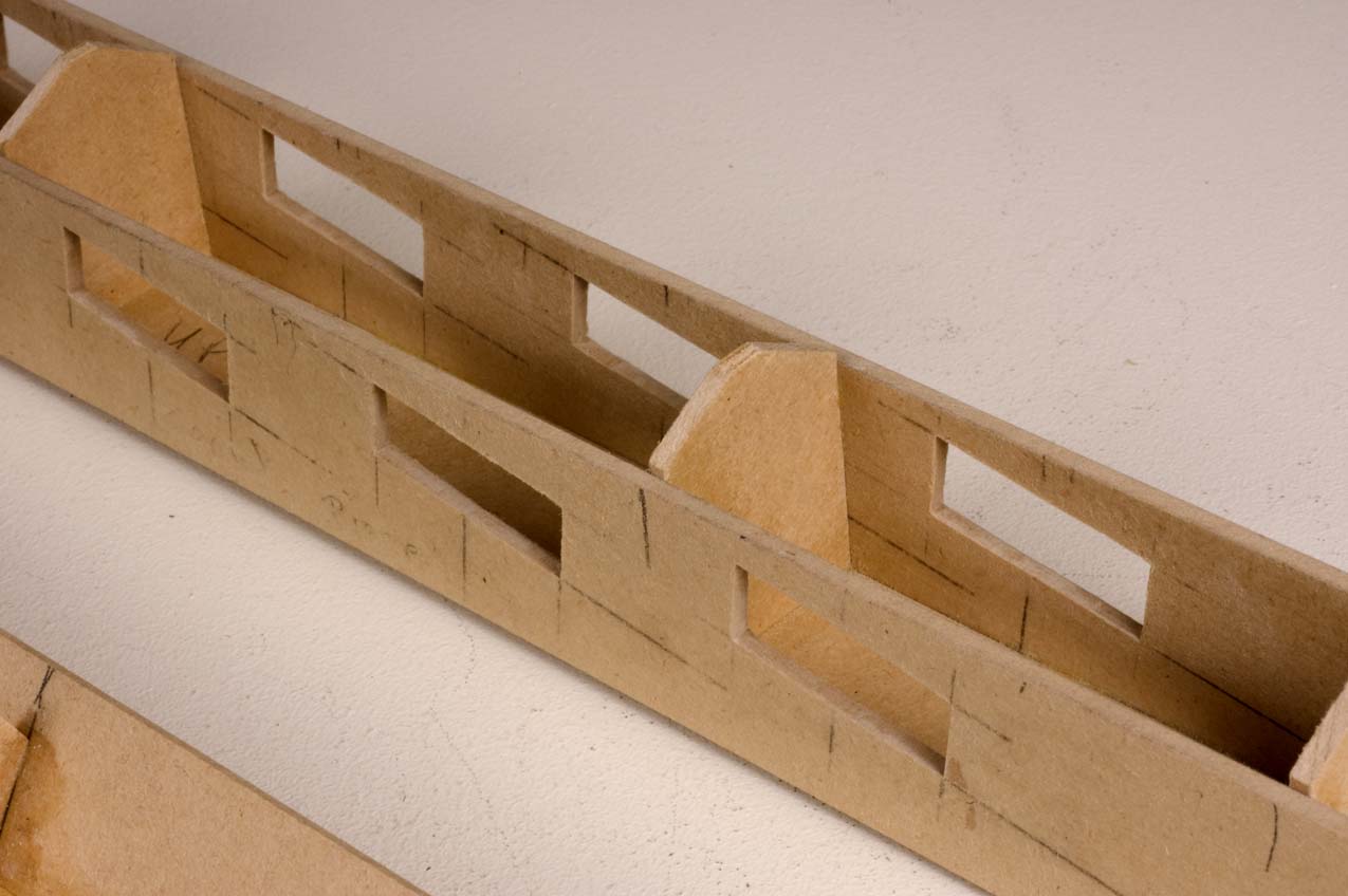 Photo 103 Here's a closer view of the conveyor house showing the pencil marks on the outer walls that were used as guides when the openings were punched out. | 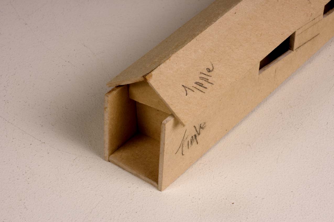 Photo 104 Note that the roof doesn't extend to the end of the head house walls. That because a small amount of the conveyor building extends into the openings in both the head house and mine. |
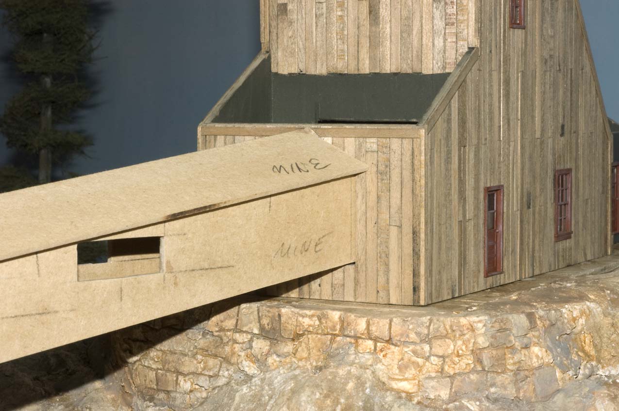 Photo 105 The conveyor house was again set in place and the ends were sanded with sanding sticks to assure a smooth and tight fit. |  Photo 106 At the head house, it was determined that notches would have to be made in a few of the batten boards to allow the conveyor house roof to fit tight against the wall. |
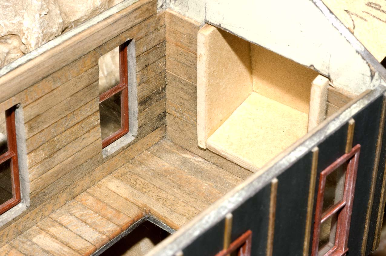 Photo 107 This view shows how the end of the conveyor house extends slightly into the interior of the head house. | 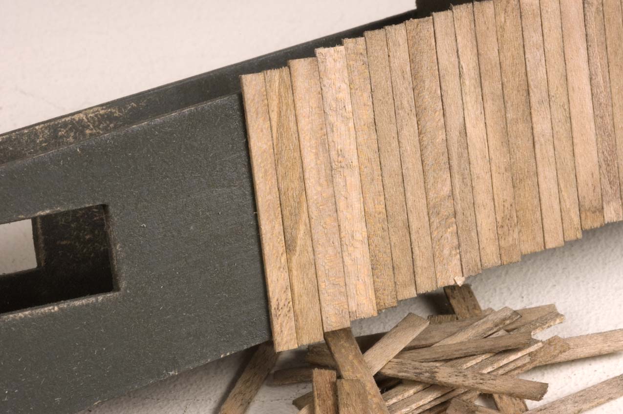 Photo 108 Stained pieces of scale 2" x 12" stripwood were glued to the sides of the conveyor house walls, completely covering the window openings and extending above and below the wall side panels. I usually use thicker than necessary stripwood siding because it's thickness will not be seen and it's much easier to handle and glue in place. |
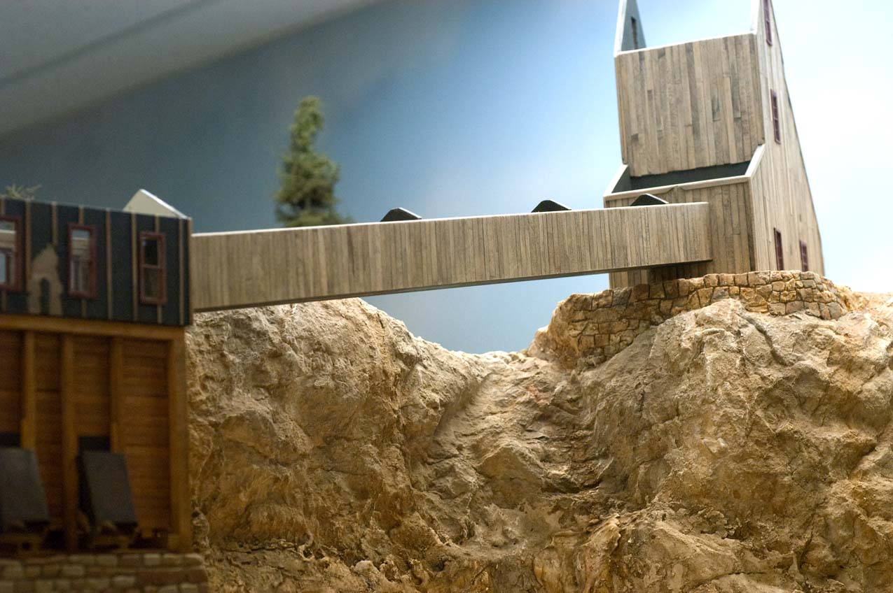 Photo 109 Here's a view of the conveyor house with the siding glued in place. The window opening still need to be cleared of excess material. | 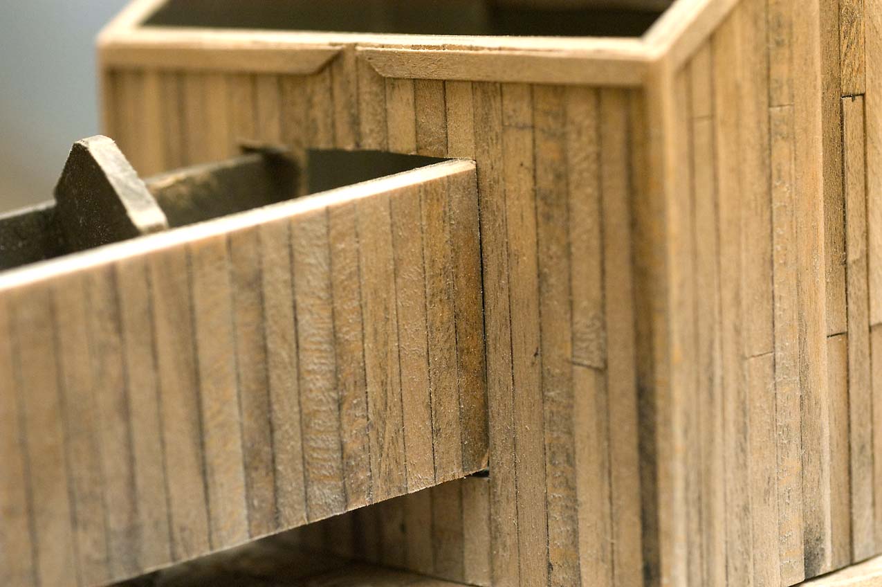 Photo 110 Adjustments in the width of the stripwood had to be made where the siding butted up against both the mine and head house. |
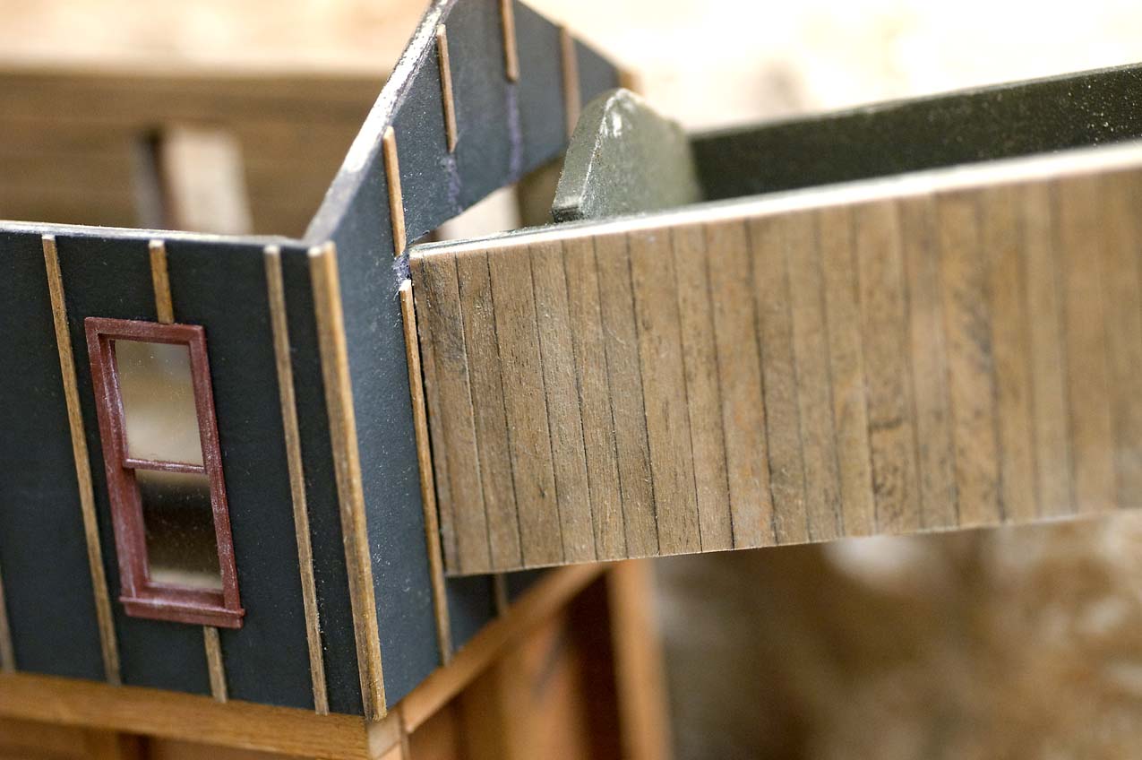 Photo 111 Note that the batten boards have been notched to clear the roof component. | 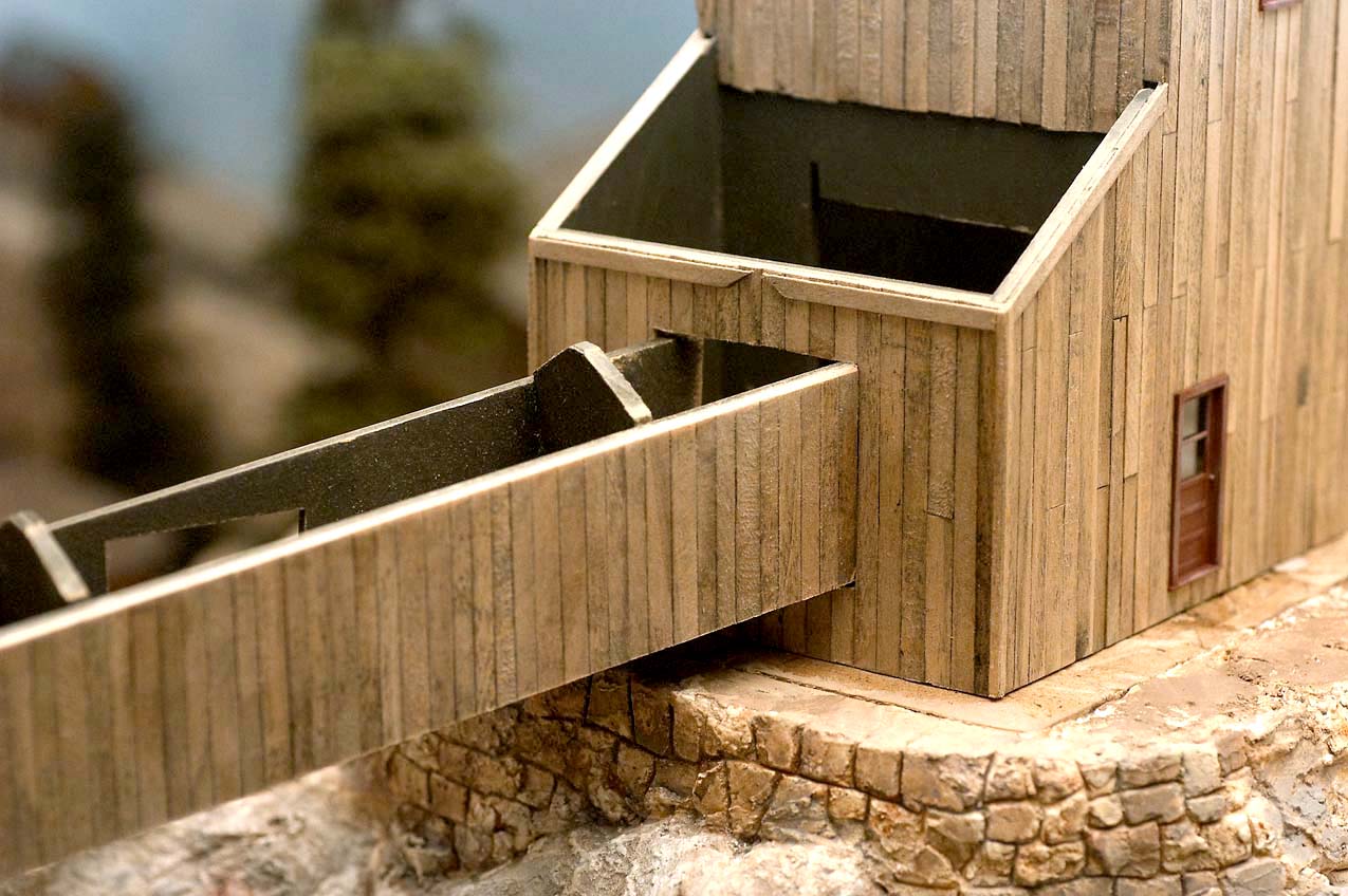 Photo 112 A small notch had to be made in the horizontal wall trim boards of the mine to clear the peak of the conveyor house roof. |
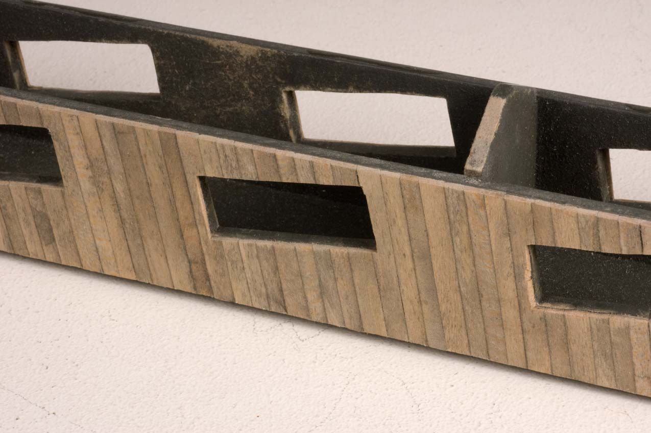 Photo 113 The excess stripwood covering the window openings has been removed and the edges of the individual boards sanded smooth with sanding sticks. | 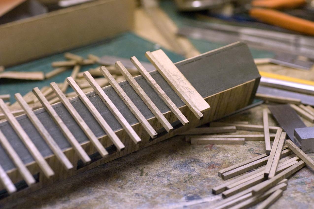 Photo 114 Square support timbers were glued to the underside of the conveyor house. A spacer was used to maintain accurate separation of the timbers. |
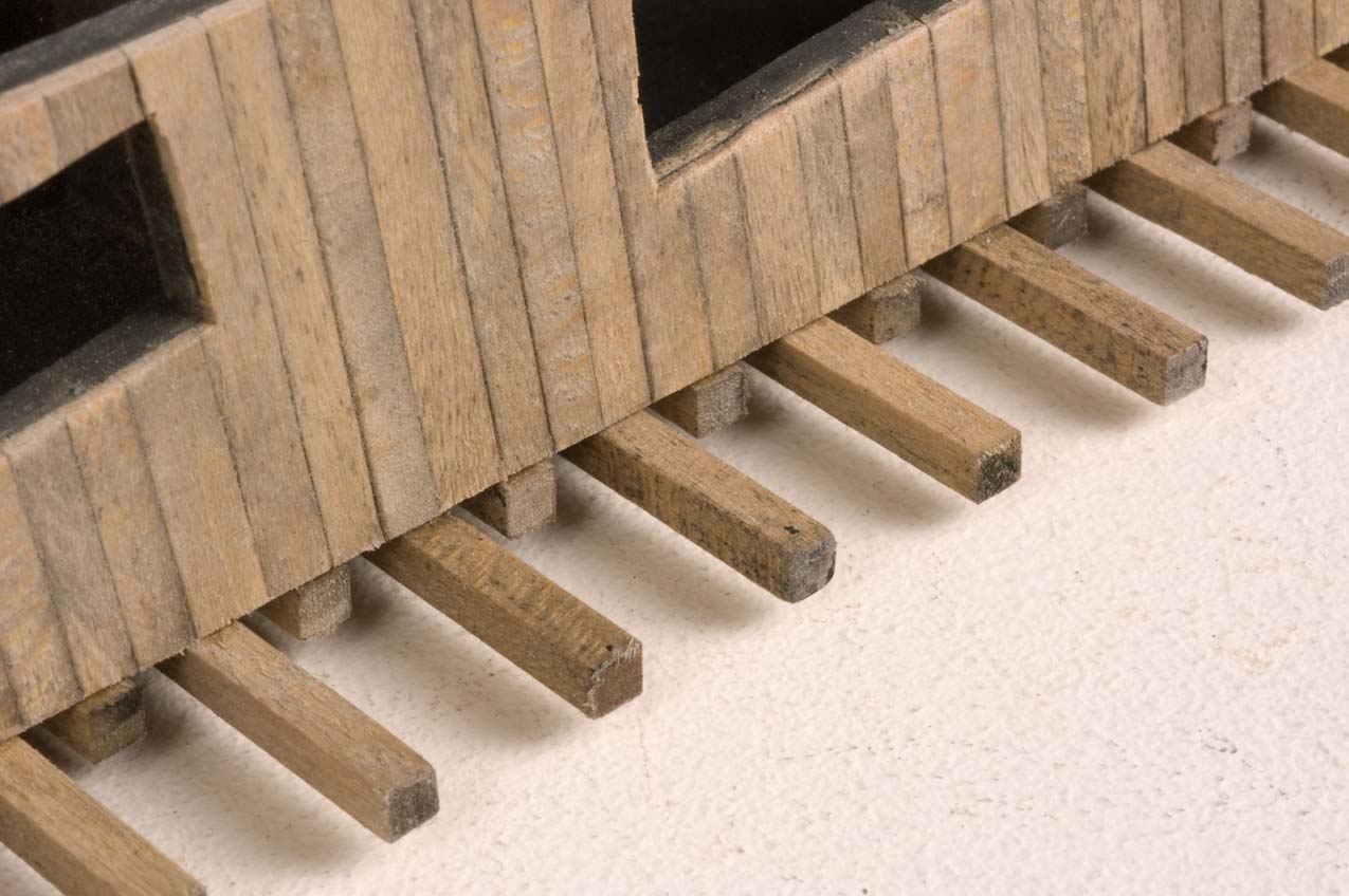 Photo 115 Longer timbers were glued between the shorter ones that extended outward to support a planked walkway. | 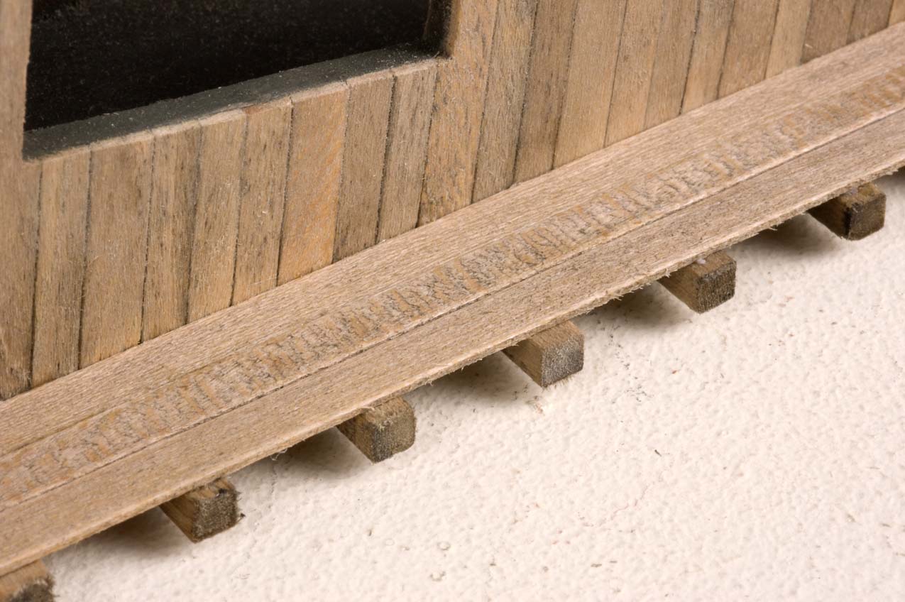 Photo 116 Three pieces of stripwood were glued to the extended timbers forming the walkway surface. The excess length of the timbers sticking out beyond the planks will eventually serve as sites where stanchions for a wire safety railing would be installed. |
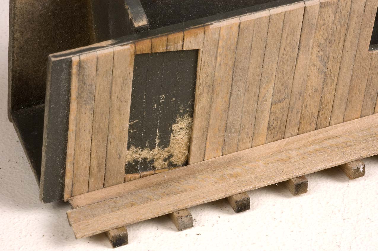 Photo 117 A few boards were removed to make way for a 3' wide door to allow miners to reach the walkway on their way to the mine. | 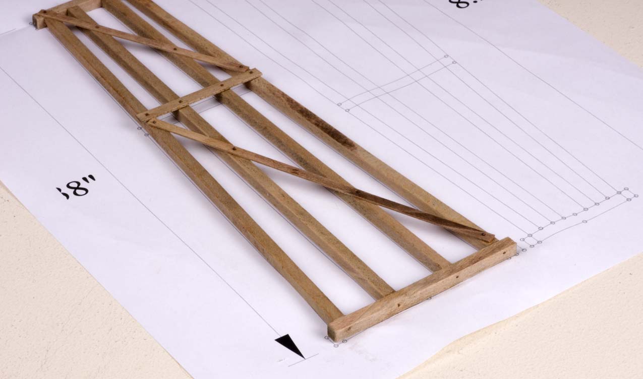 Photo 118 Drawings for the timber bents to support the conveyor house were made with CADRail and printed out on heavy card stock and used as gluing templates. Their locations under the conveyor house were predetermined using a metal ruler and the large drafting triangle to assure that they would be vertical. |
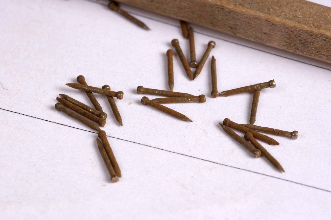 Photo 119 Close up view of the 1/4" long brads used to reinforce glue bonds on the trestle bents. | 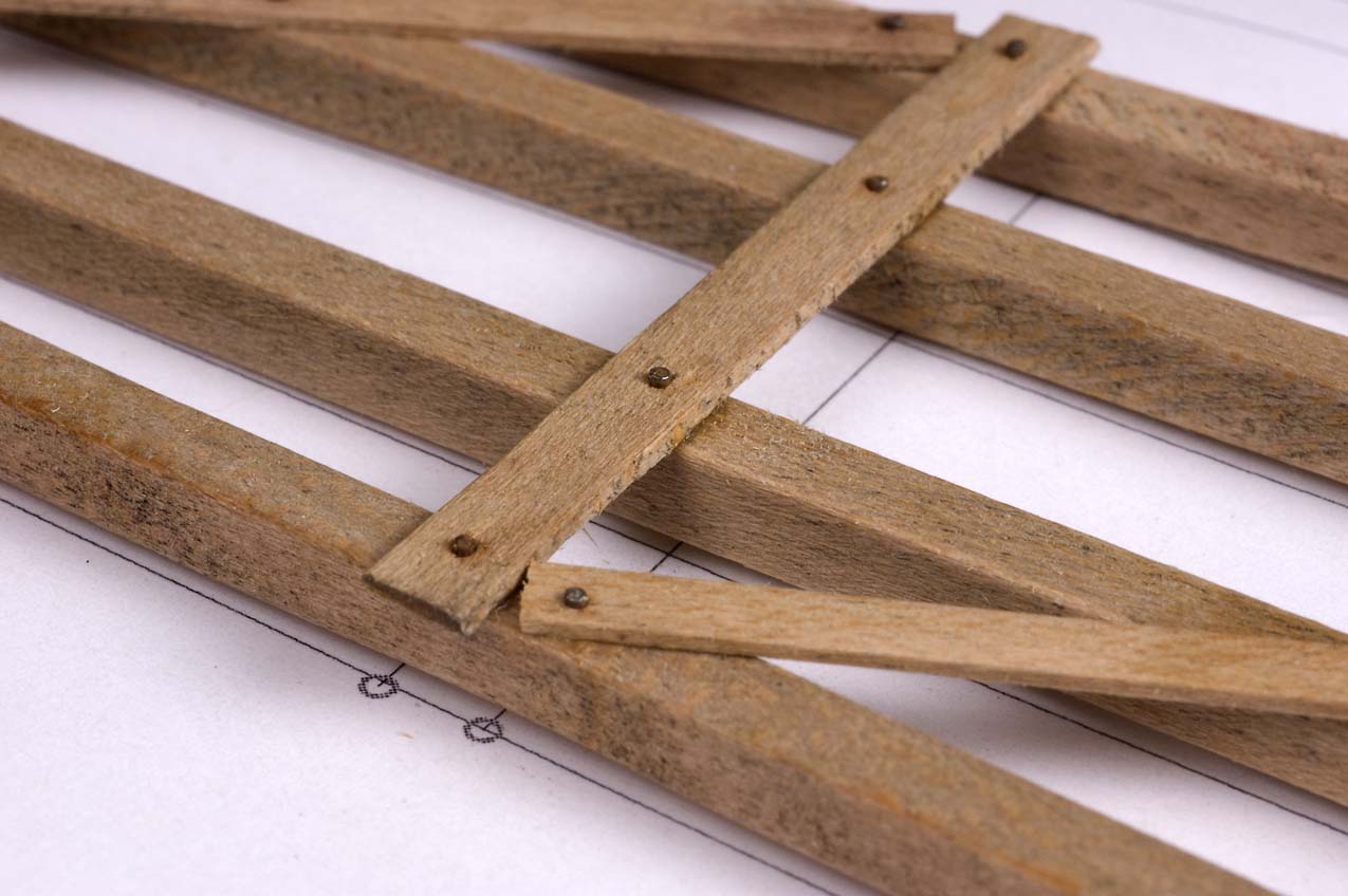 Photo 120 A 1/4" brad was inserted at virtually every site where timbers were attached. |
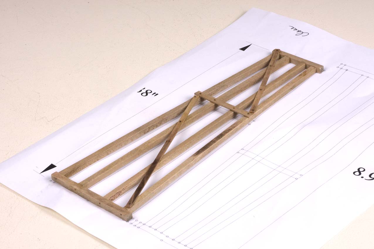 Photo 121 From a short distance away, the brads take on the appearance of a NBW casting. | 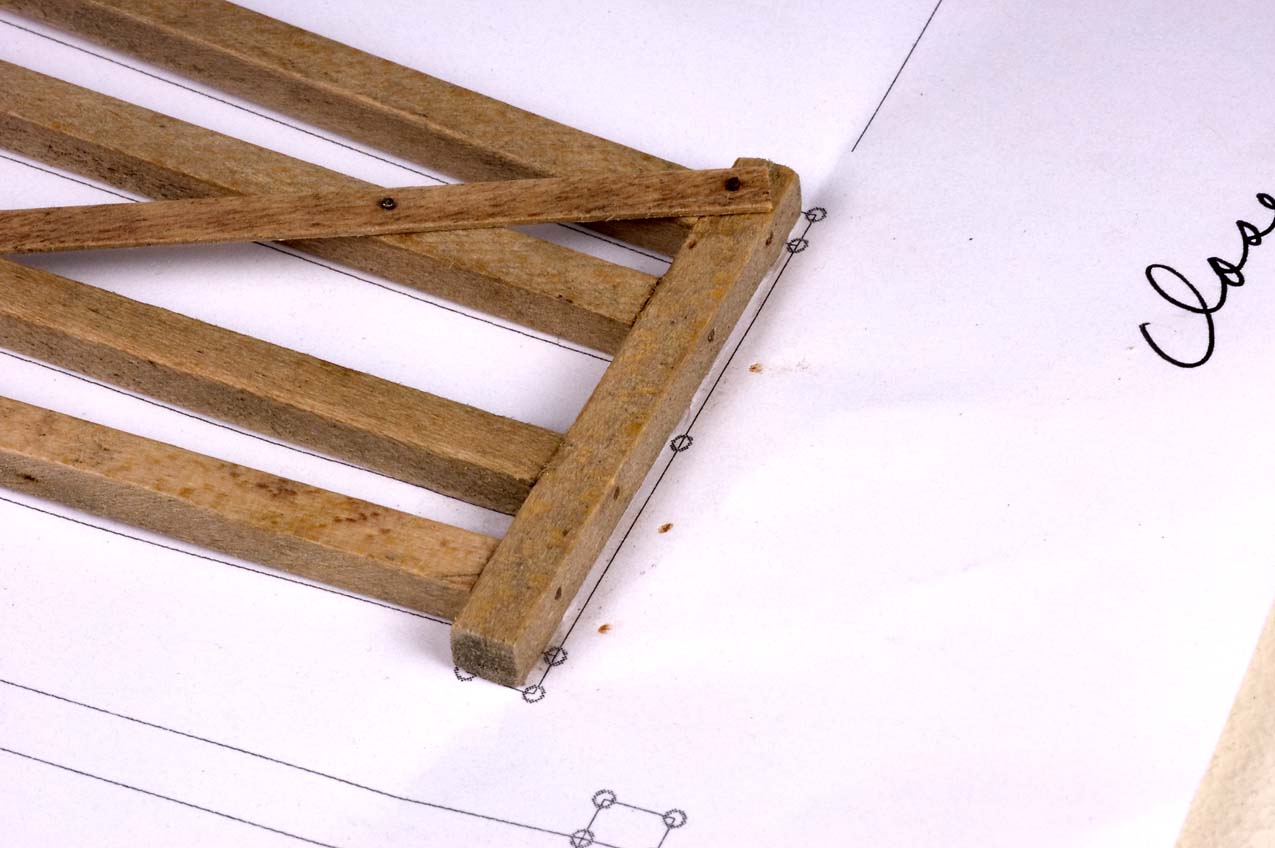 Photo 122 The larger horizontal timbers were fastened to the ends of the vertical timbers with 1/2" long brads. |
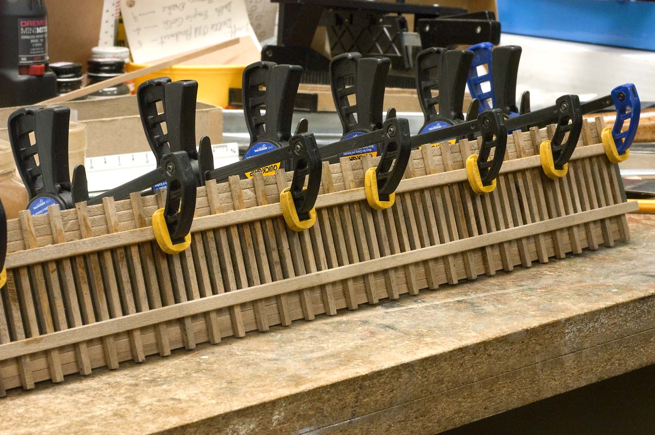 Photo 123 Two long square timbers were glued to the underside of the smaller square timbers. These represent the stringers that will rest atop the timber bent components. Again, plenty of clamps were used to fasten them in place. | 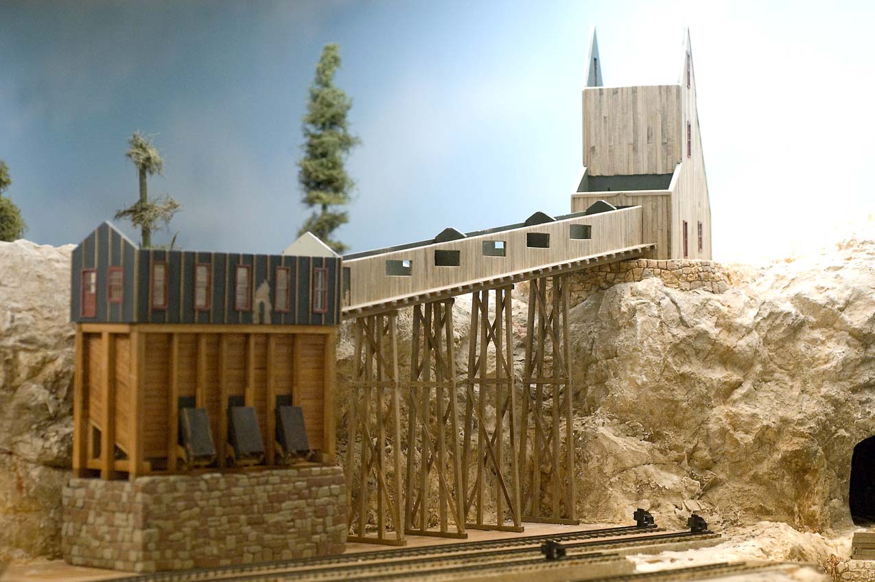 Photo 124 Here's a progress photo with the three major components of the mine complex in position. |
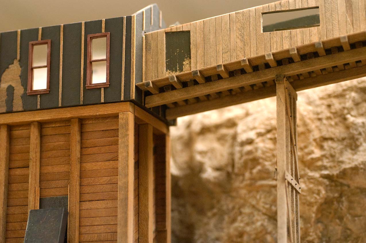 Photo 125 This bunker end view shows that a large supporting timber still needs to be attached to the building to support the conveyor structure. | 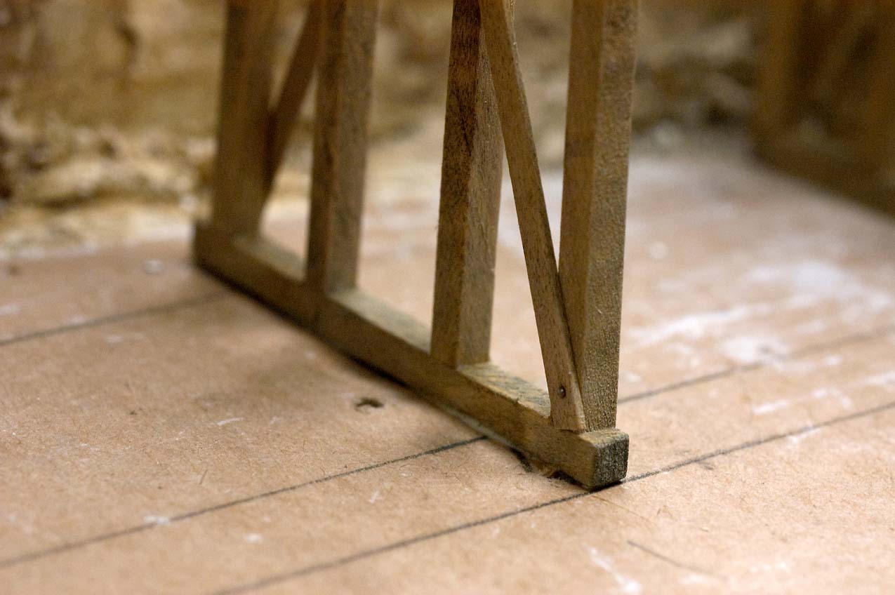 Photo 126 If you look closely, a small piece of shim material can be seen under the front edge of the timber bent. |
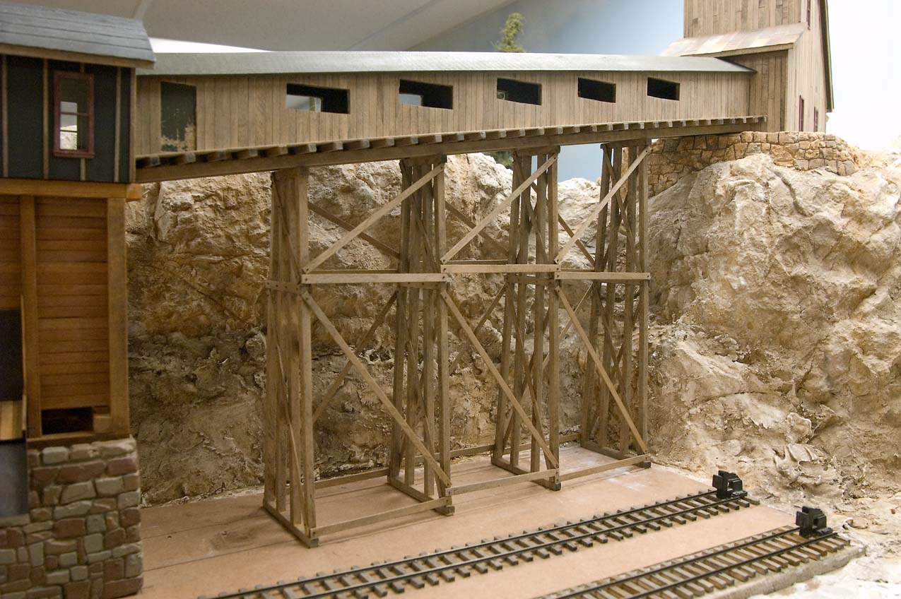 Photo 127 Once I was satisfied with the fit and placement of the trestle bents, horizontal boards were attached to tie the four bents together. Their bases were then secured to the Gator Board base. | 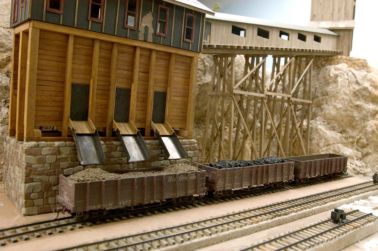 Photo 128 Three high side gondolas were spotted on the loading spur to give me an idea of how things were going to look. |
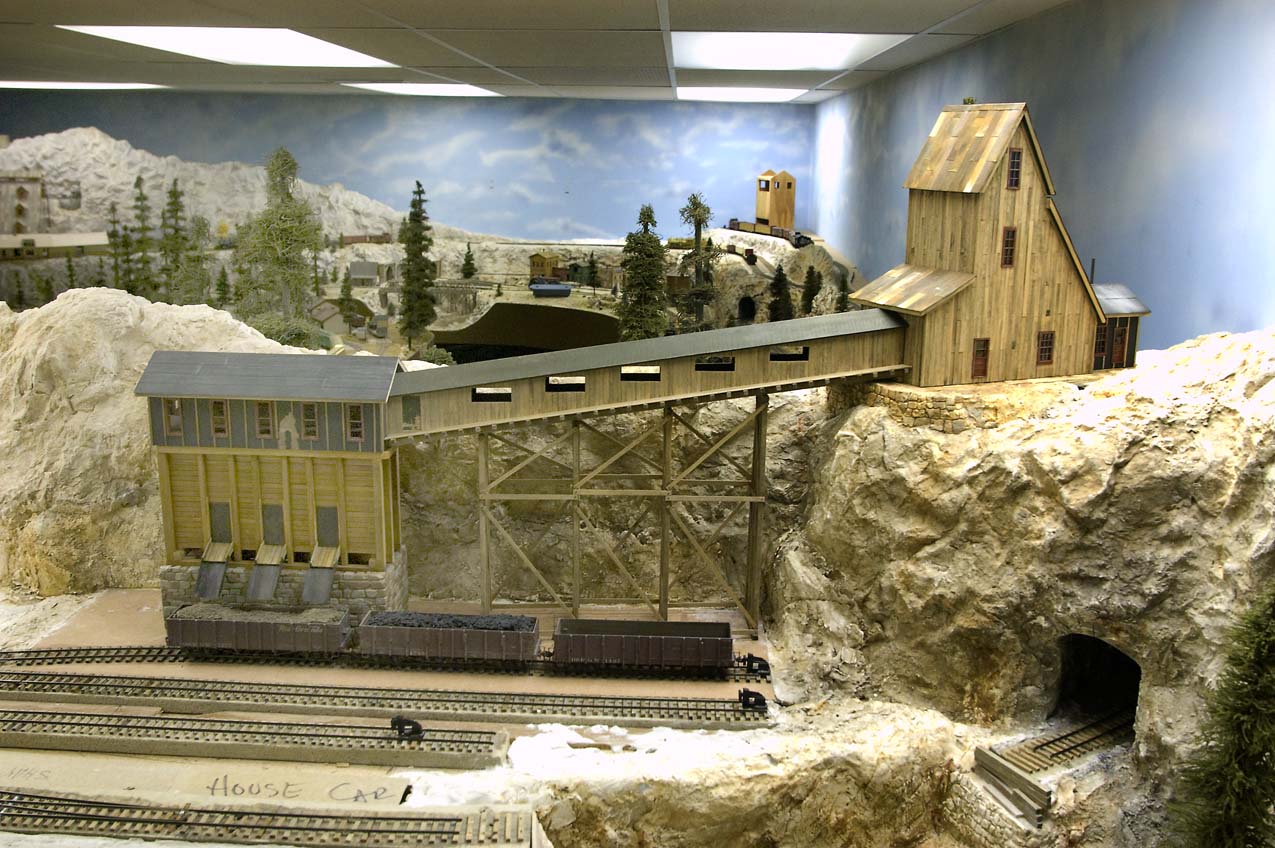 Photo 129 I couldn't resist taking a photo of the scene from high above the new mine scene. |  Photo 130 I couldn't resist taking a photo of the scene from high above the new mine scene. |
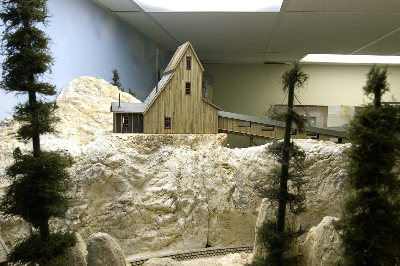 Photo 131 This view from the other side of the mountain illustrates how impressive the new mine is going to appear as it rests near the top of the mountain. | 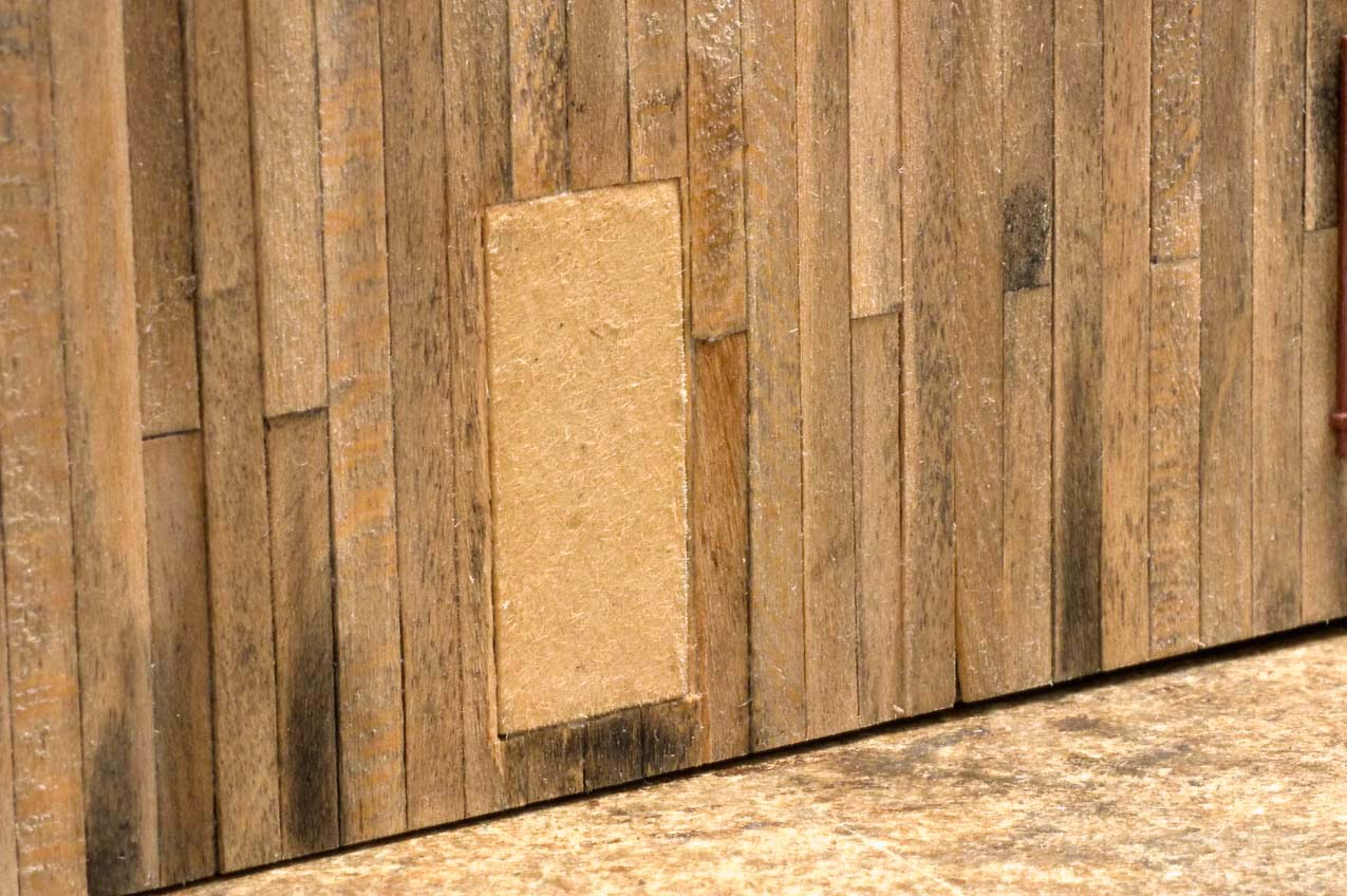 Photo 132 This and the following five images were made after the mine complex had been installed on the layout for a short time. I realized that I had not provided any means for miners to bring heavy materials up to and into the mine building. Since we're still working on the mine building, I decided to insert these images here to illustrate how I fixed that problem by removing the original 3' wide door and replacing it with a 6' wide sliding door. To create a smooth surface for the new door, the original door was pried out and its hole was plugged with a piece of the 1/8" thick fiber board. |
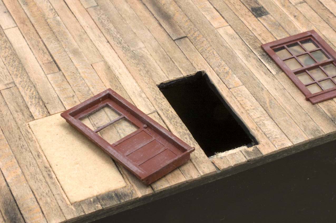 Photo 133 To create a doorway for the miners, a new opening was carefully carved out of the fiber board a few scale feet to the right of the original opening. | 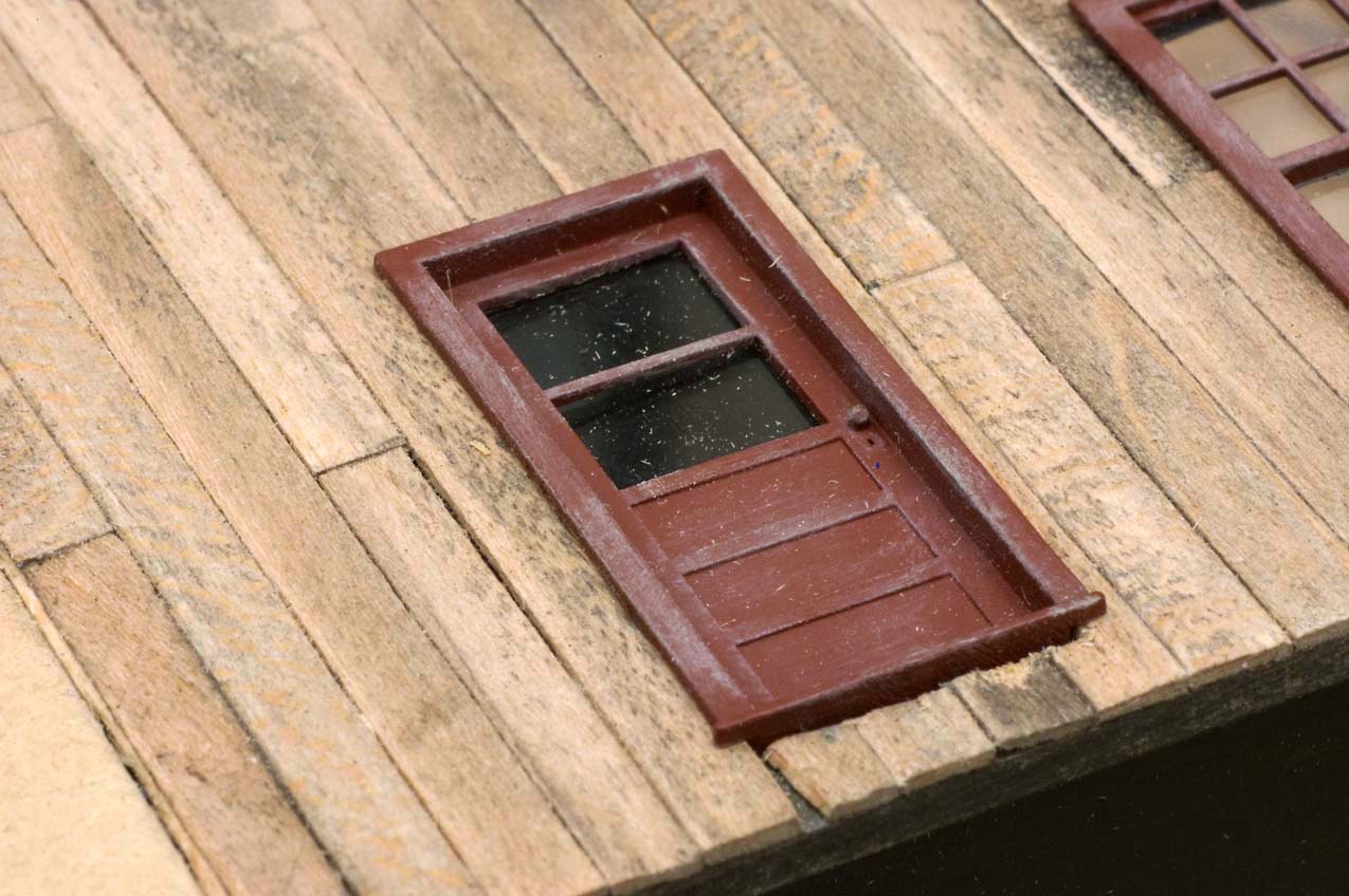 Photo 134 After the edges of the new opening were sanded smooth, the door casting was glued in place with Aleene's Tacky Glue. |
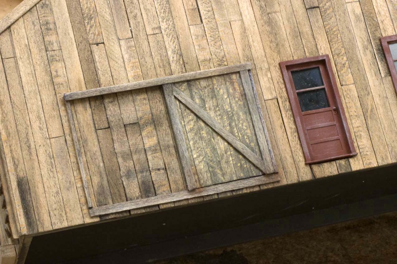 Photo 135 A new 6' wide door was scratch built out of stripwood and glued in a closed state over the fiber board plug added earlier. | 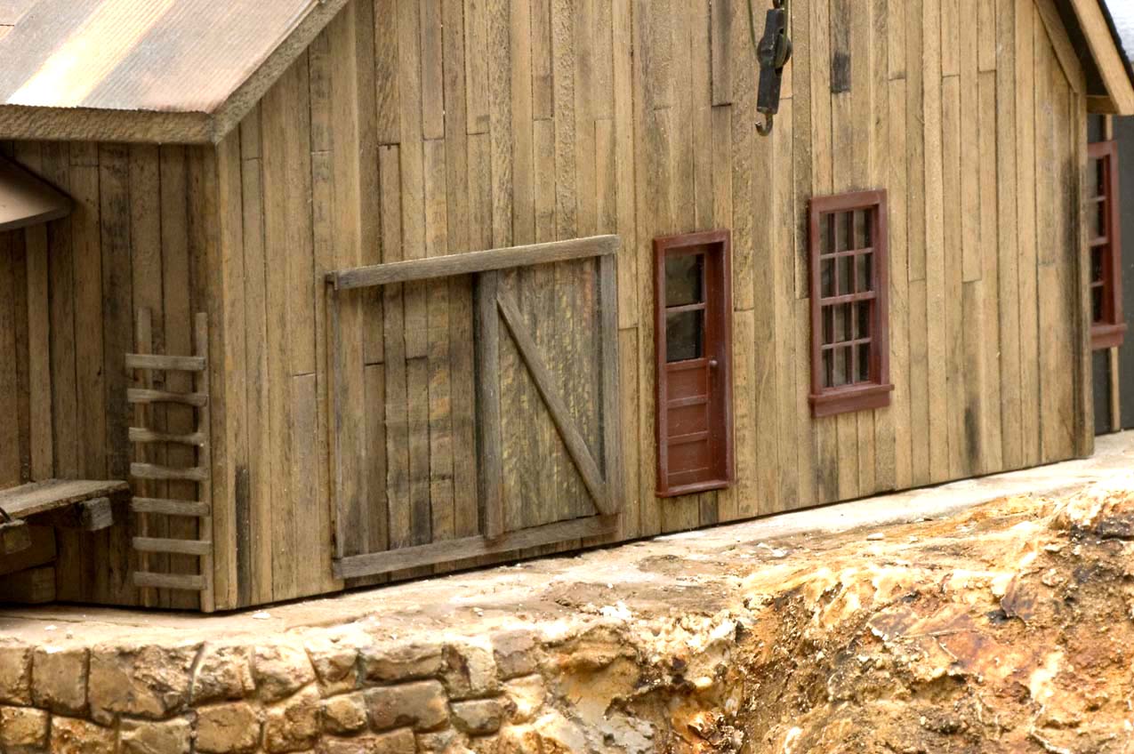 Photo 136 A wooden frame work was fabricated above the new door to suggest a protective cover for the track and door rollers. |
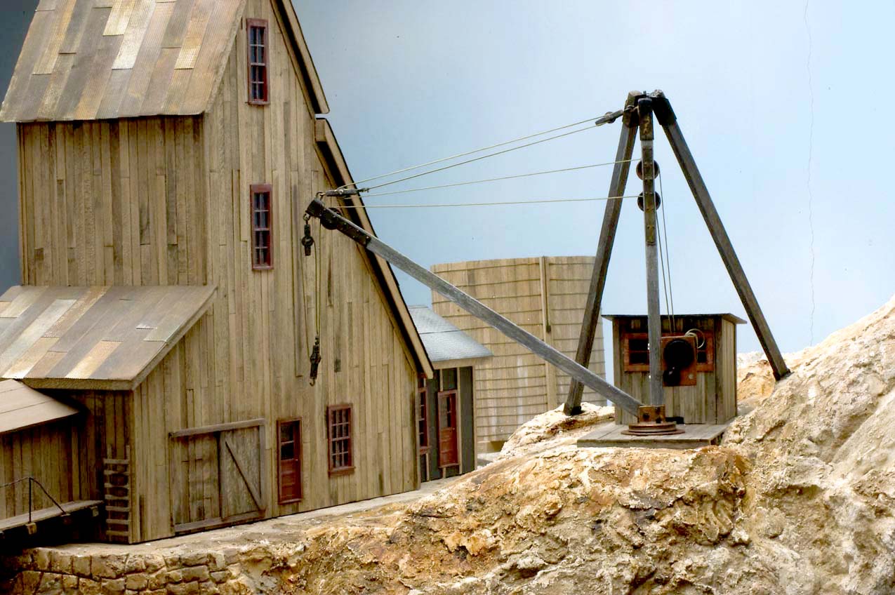 Photo 137 The new door is in place along with a stiff leg derrick that I scratchbuilt to add to the scene. | 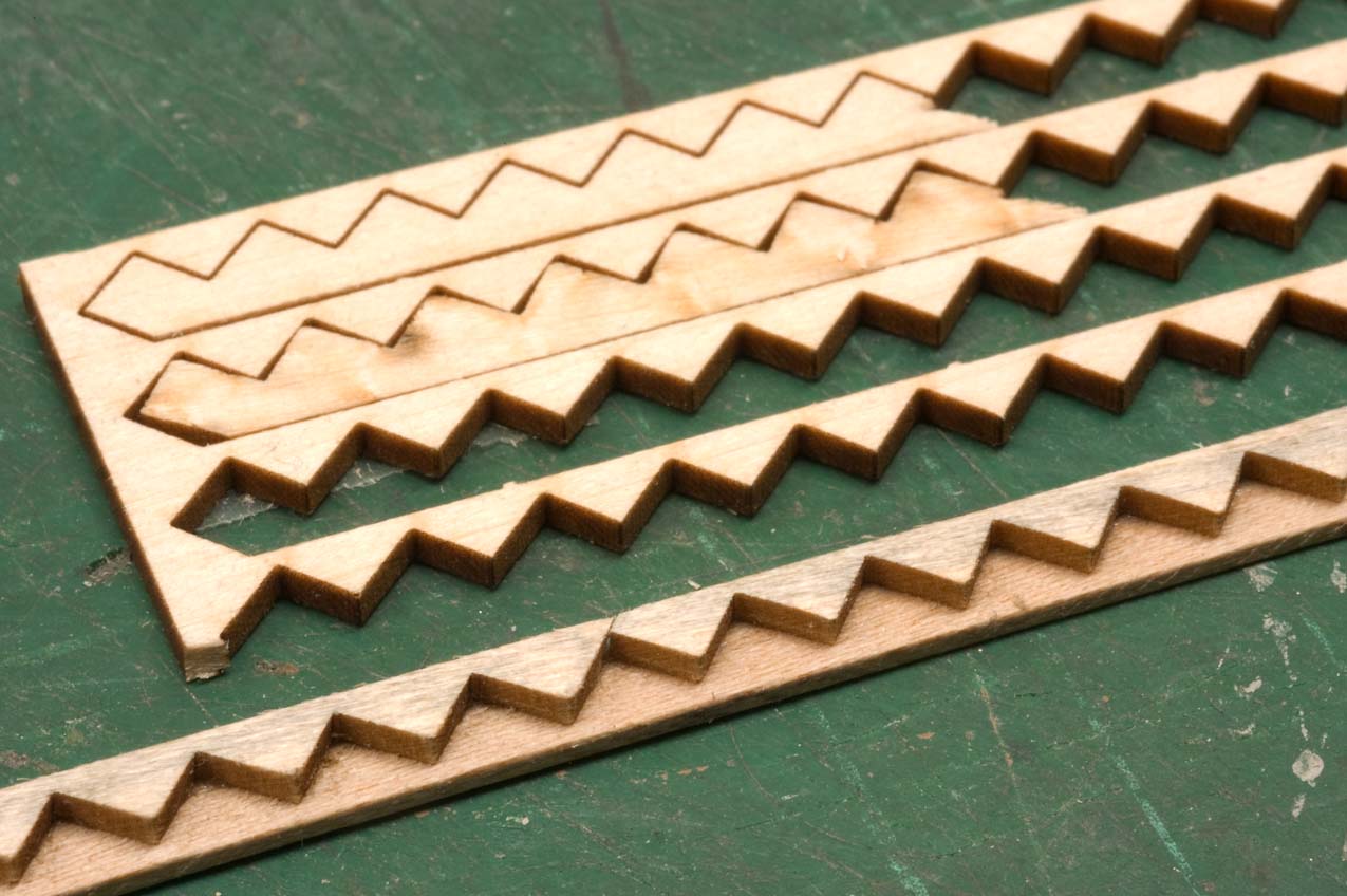 Photo 138 With the conveyor and mine buildings almost complete, it was time to provide a way for the miners to reach the mine. I decided to make a series of staircases and landings at the other end of the bunker component. It involved a rather complex process, but I wanted to provide a safe way for the miners to get to and from work. The process involved using pieces from the carrier sheet left over from a previously completed Banta Modelworks stairway structure |
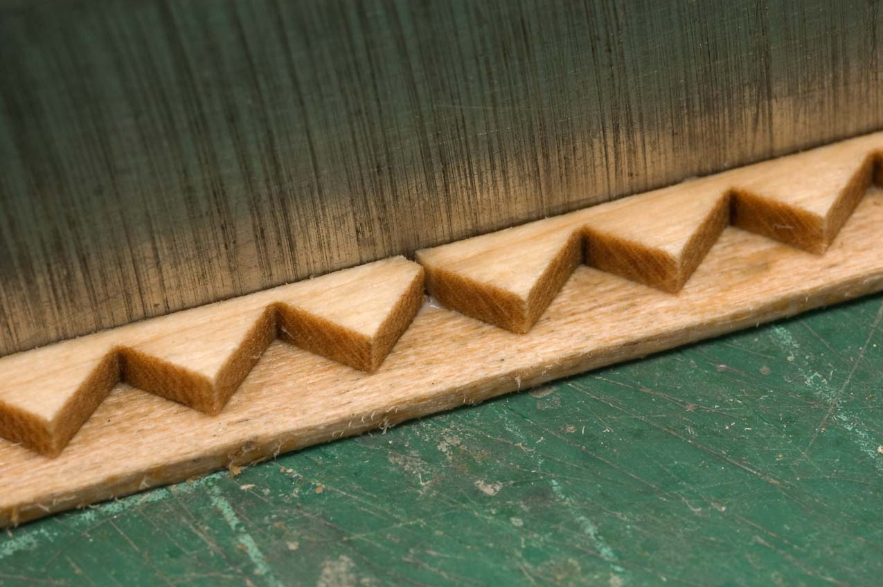 Photo 139 Boxed stair stringers were made by gluing pieces of the normally discarded laser cut parts to a strip of stripwood. | 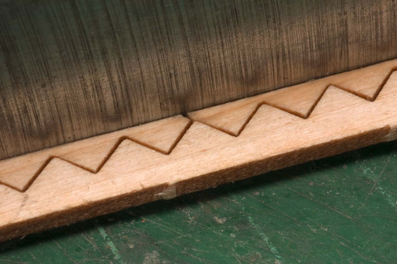 Photo 140 To make sure the spacing of these tread supports was correct, a piece of stair stringer was used to check the alignment. |
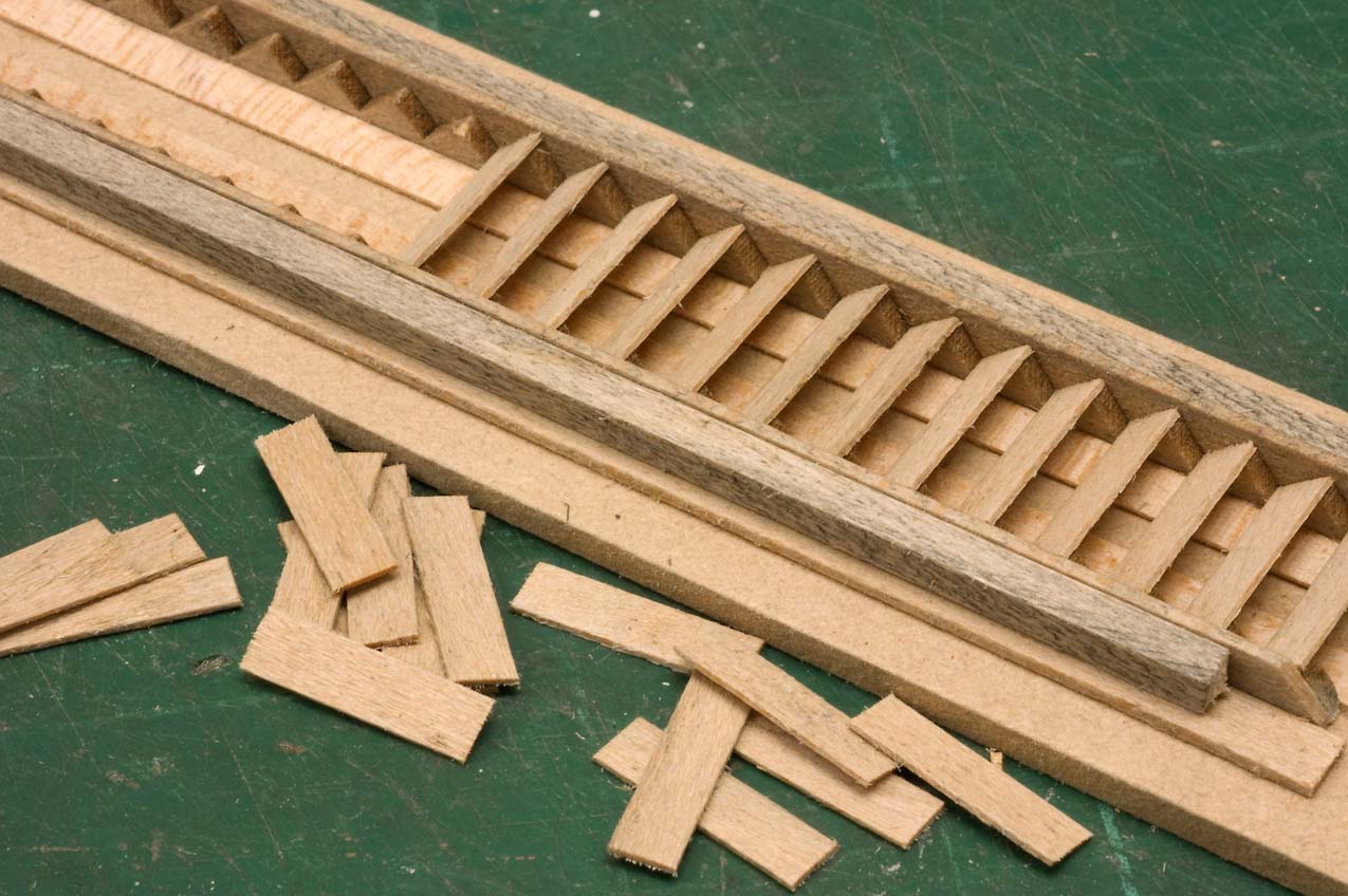 Photo 141 A NWSL Chopper was used to cut the individual stair treads which were then glued to the boxed stringers using an alignment fixture made from scrap pieces of stripwood. | 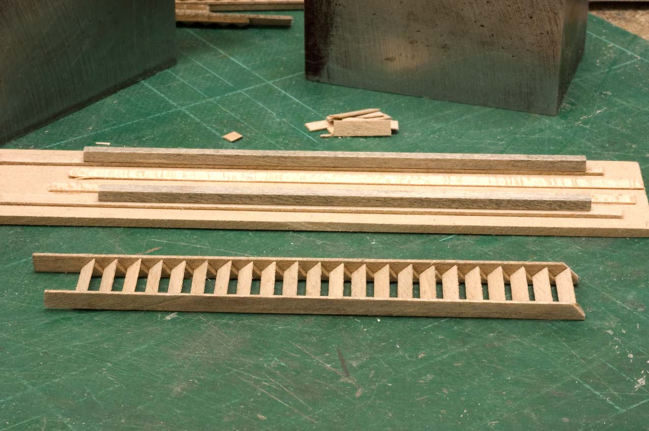 Photo 142 Once the glue had set, the completed stair component was pried from the fixture. It was built slightly longer than necessary to allow for precise fitting when it was being set into position. |
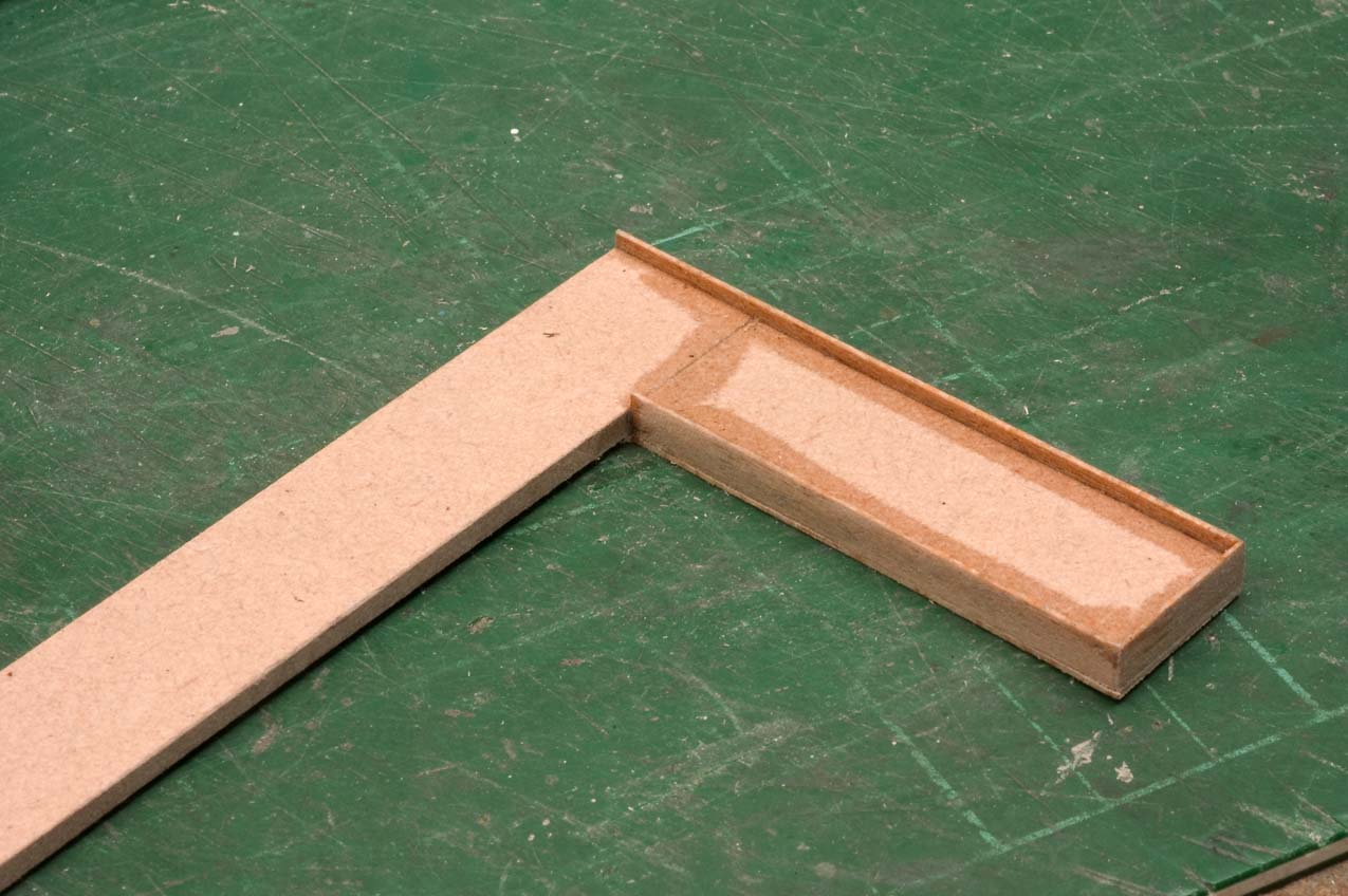 Photo 143 The interior support for the upper landing was made from two pieces of the 1/8" thick fiber board. Another piece of stripwood was attached across the front edge to reinforce the glue bond. | 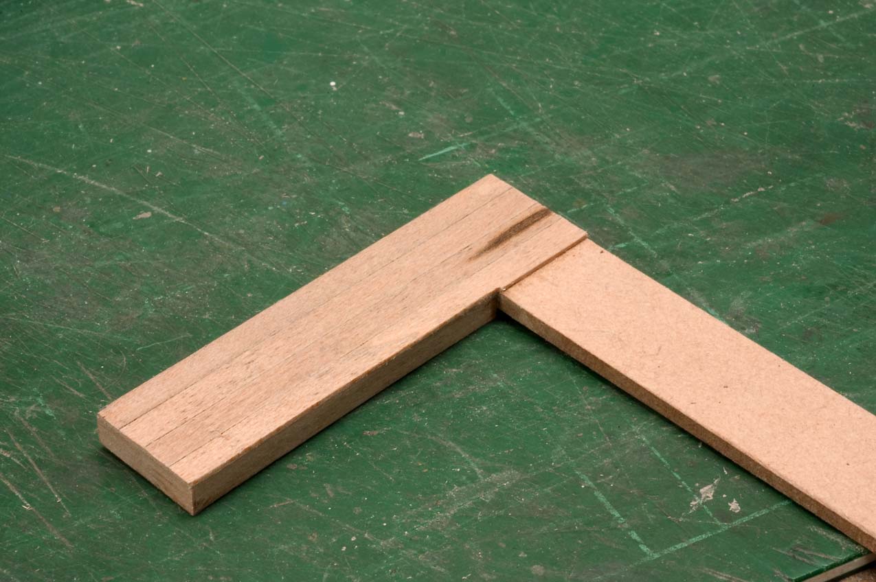 Photo 144 It was turned over and additional timbers were glued in place to represent the walking surface. |
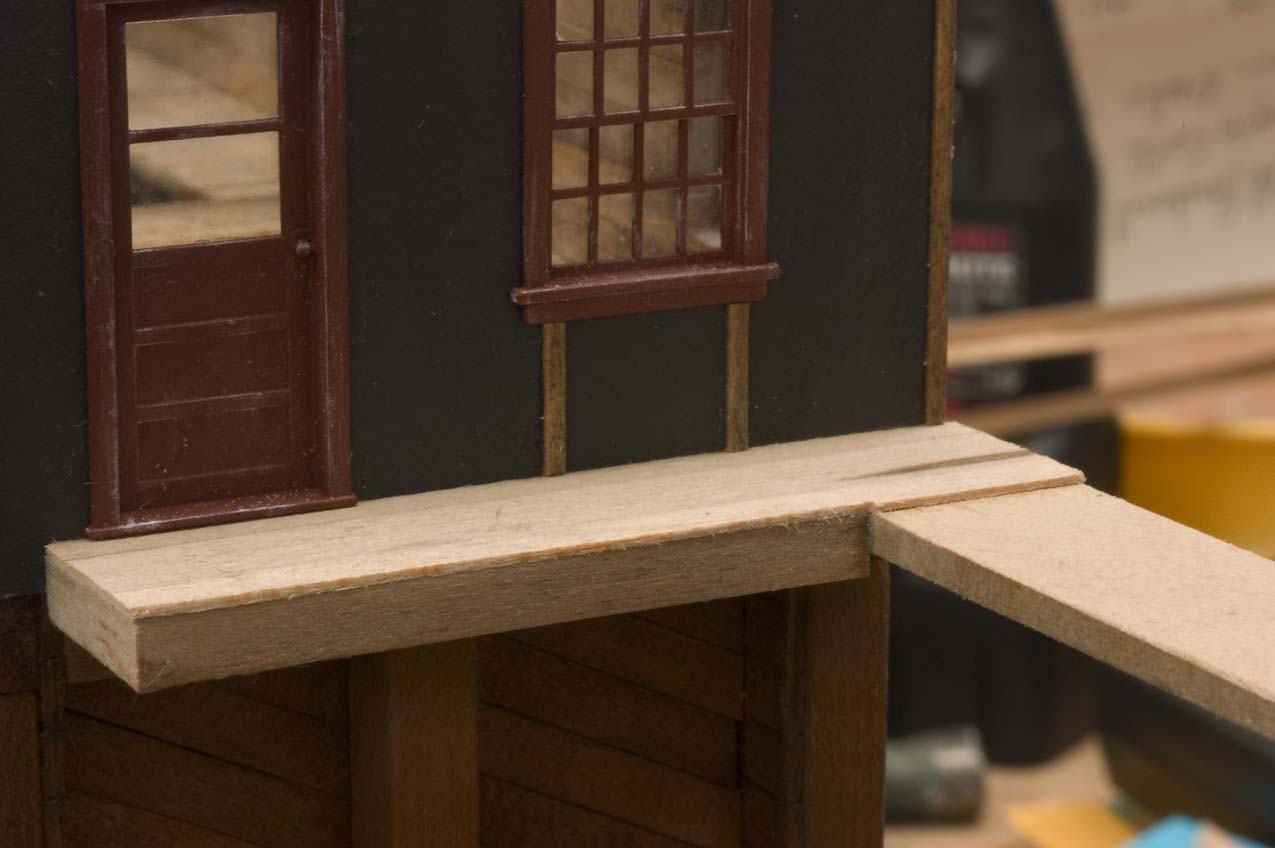 Photo 145 The upper landing was glued to the edge of the upper edge of the ore bunker, being careful to not glue it to the head house. | 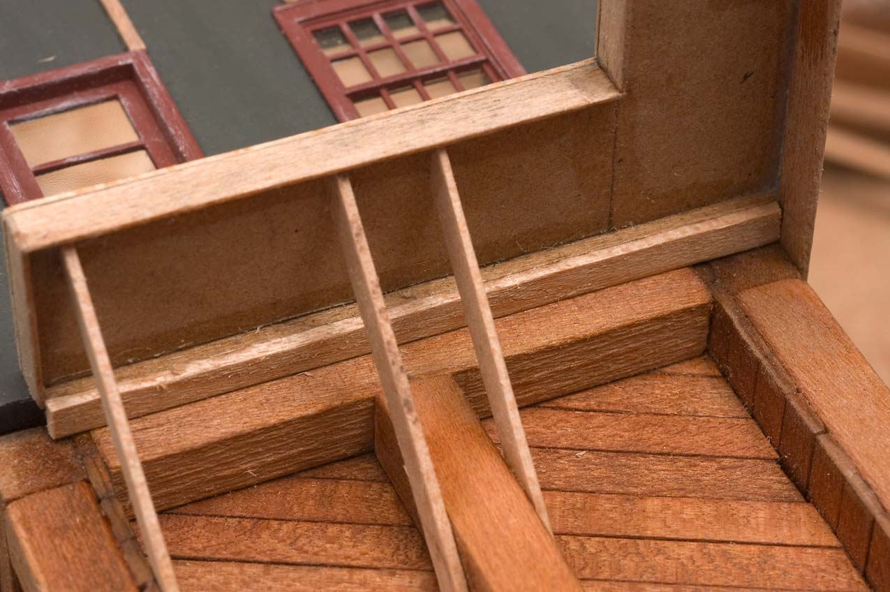 Photo 146 A small piece of square stripwood was glued under the lower edge to reinforce the connection. Three diagonal braces were also added for additional support. |
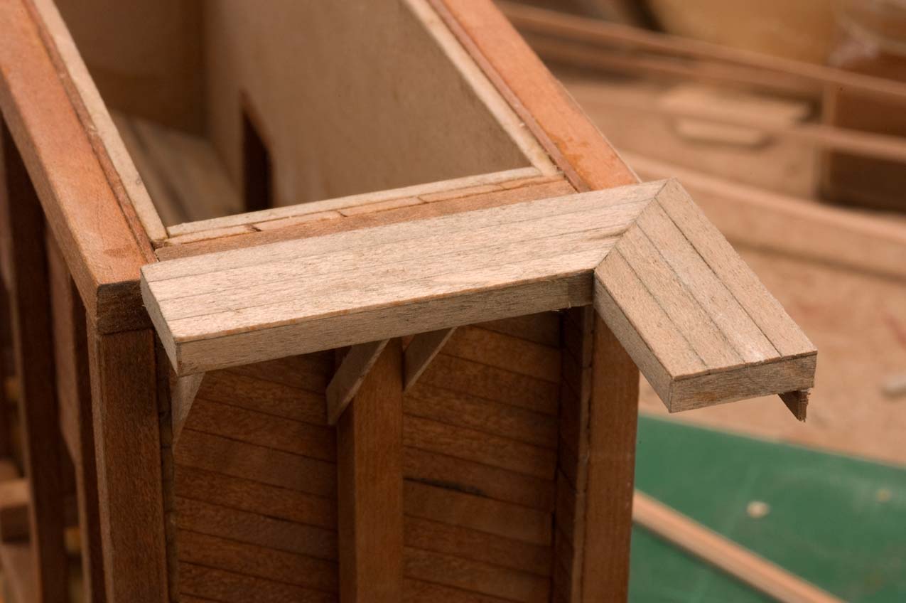 Photo 147 Four pieces of decking were cut, fitted and glued to the short end surface to complete the decking for this upper landing. | 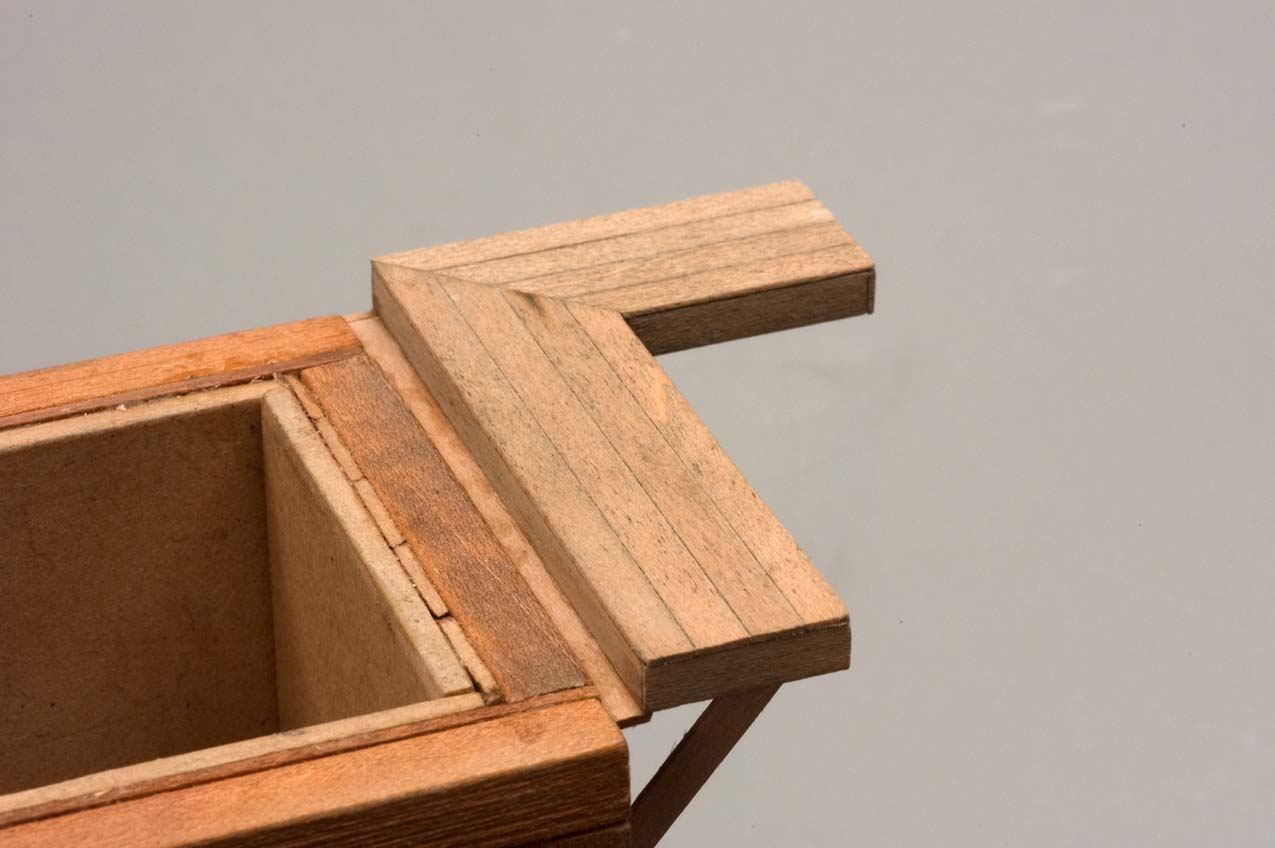 Photo 148 This view shows the amount of offset needed for the landing to allow the head house to nestle tightly in place. |
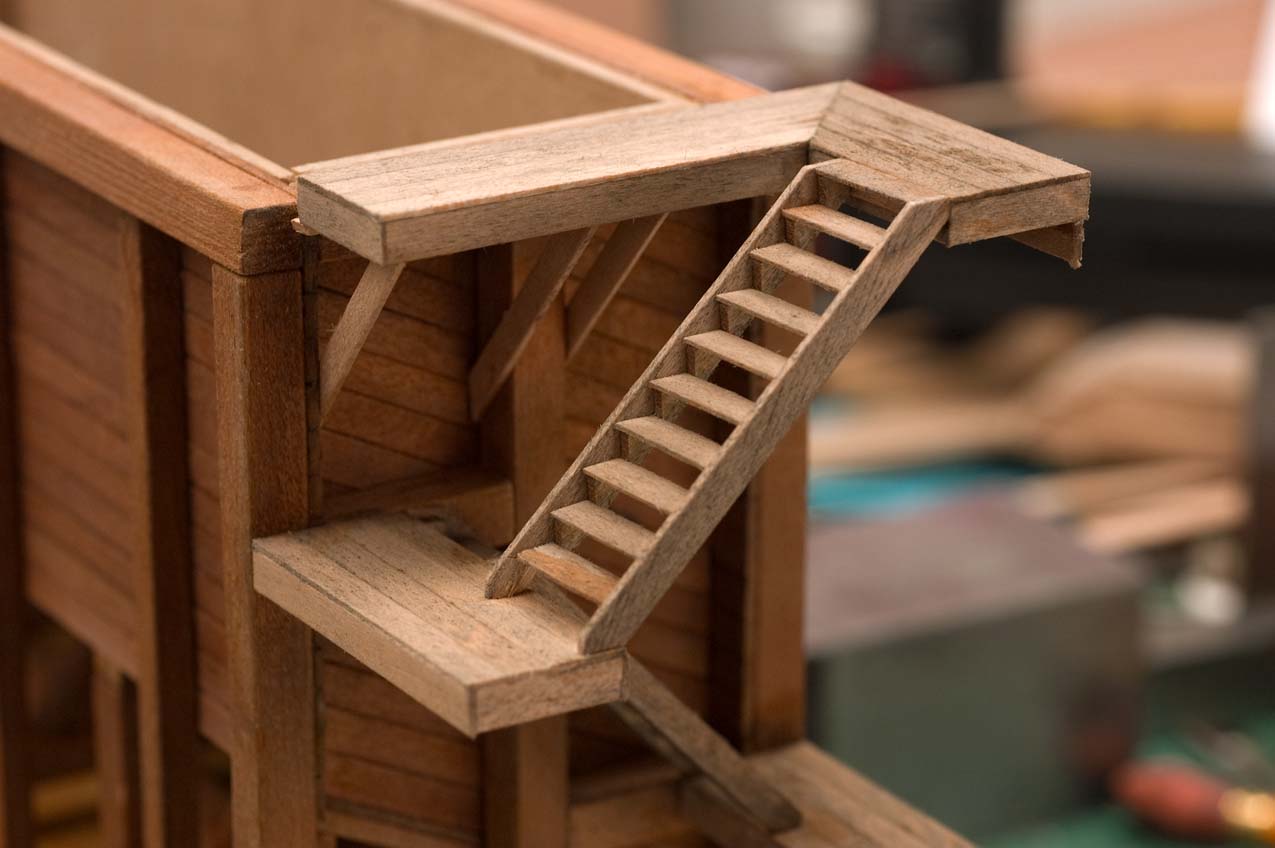 Photo 149 With the top landing firmly in place, the next one down was located and glued in place. Then one of the boxed stringer sets was trimmed to fit and glued in position. | 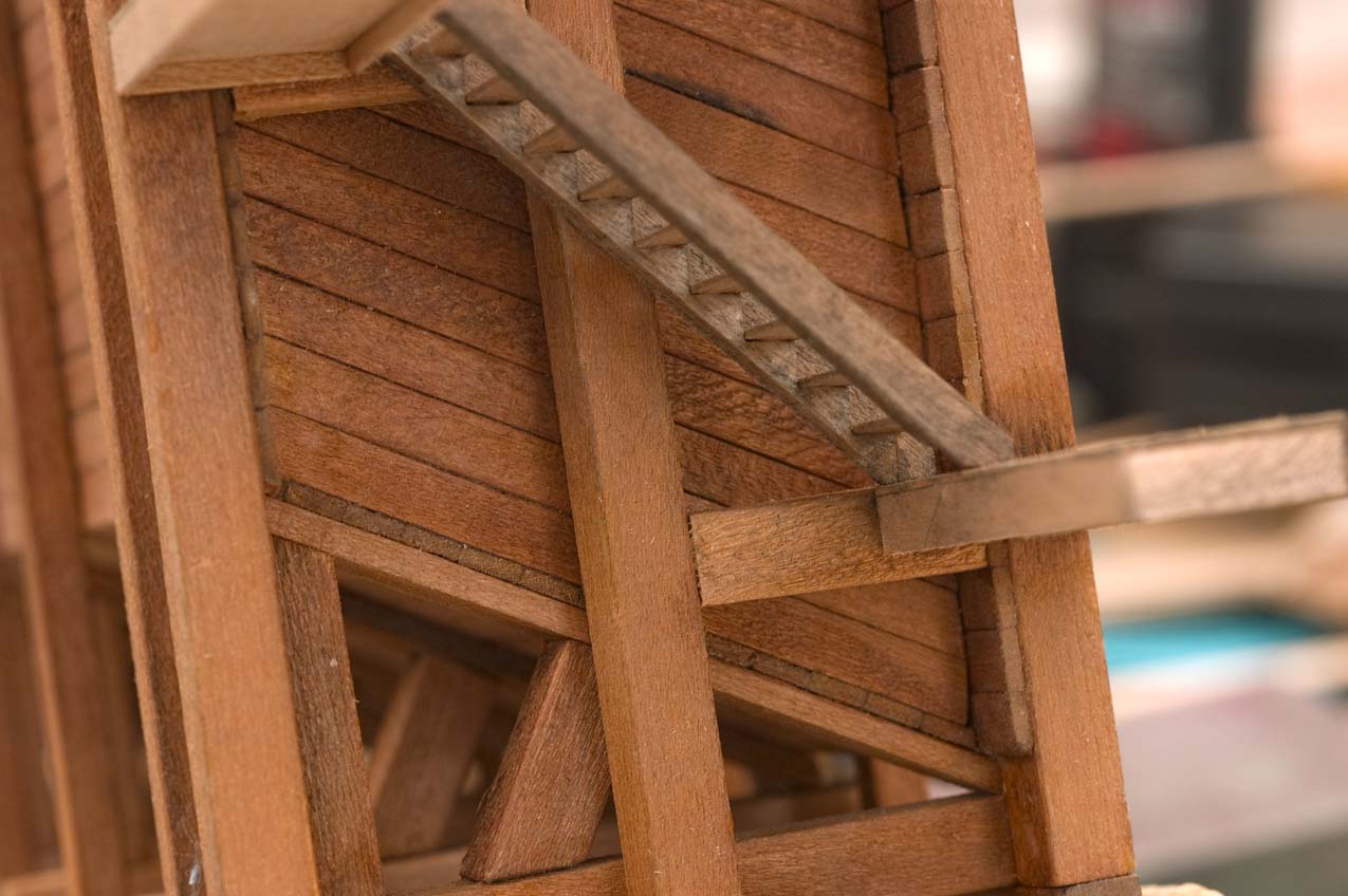 Photo 150 This underside view shows how and where the edges of the stair landings were fastened to the ore bunker. |
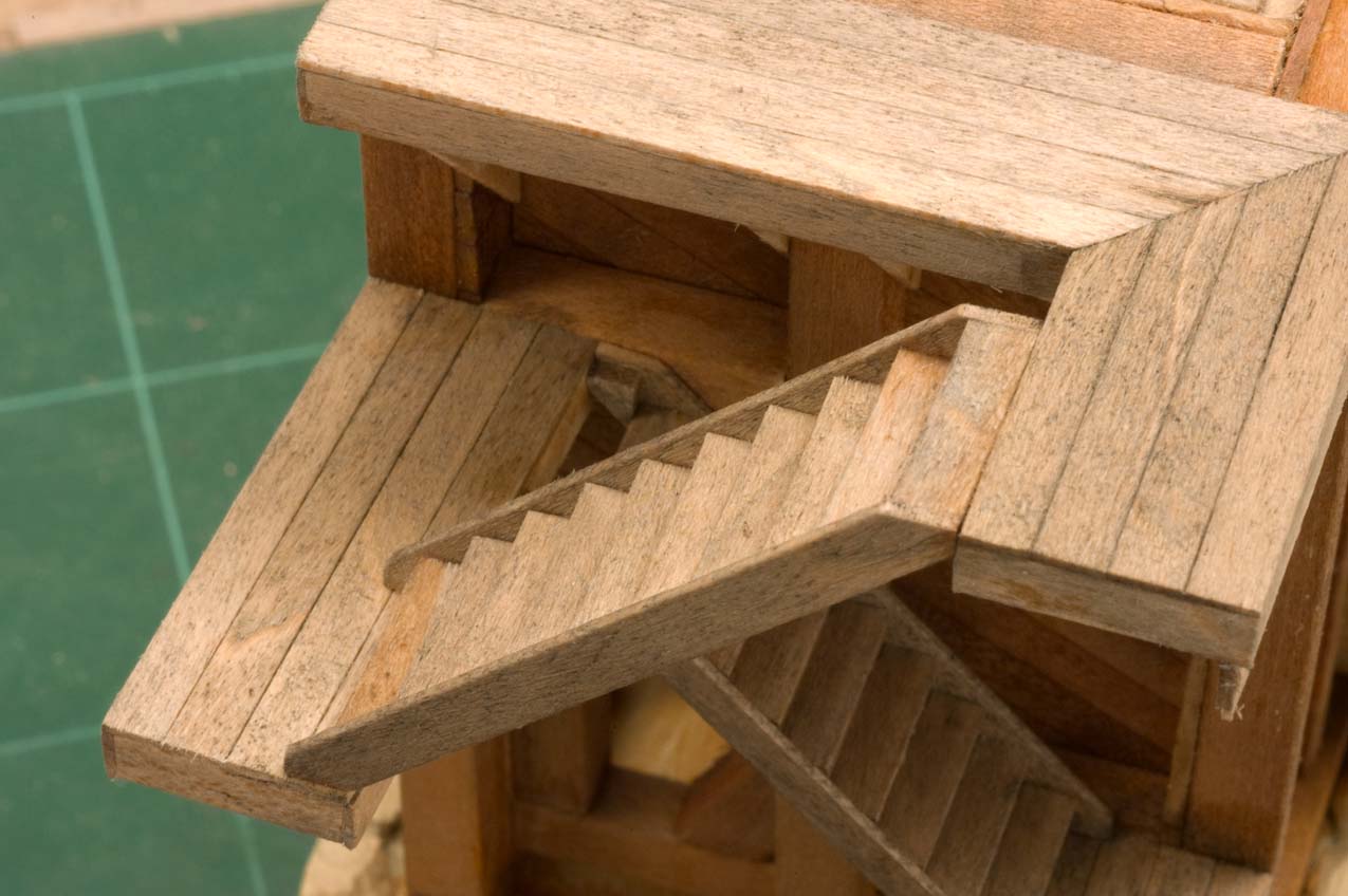 Photo 151 The structure was fairly fragile at this point and I had to be extremely careful to not dislodge anything. | 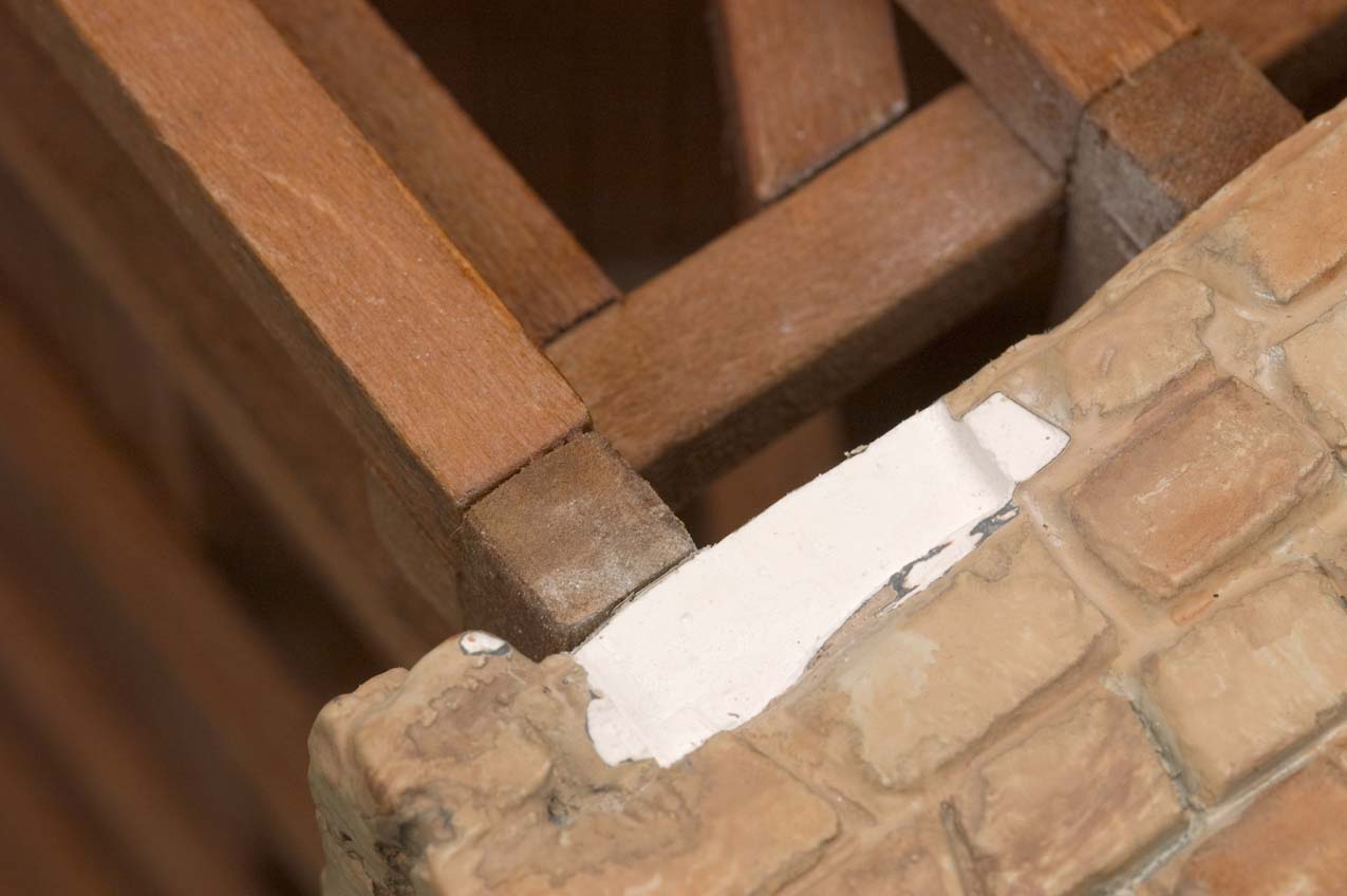 Photo 152 Some of the plaster rock castings had to be scrapped away with the edge of a flat carving chisel to make a place for the next landing component. The carved area was painted with craft paints to match the surrounding stones. |
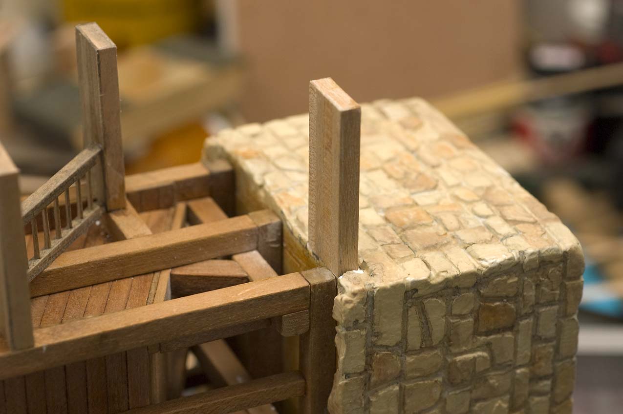 Photo 153 This final landing, was glued in place with yellow glue and left alone to dry completely. | 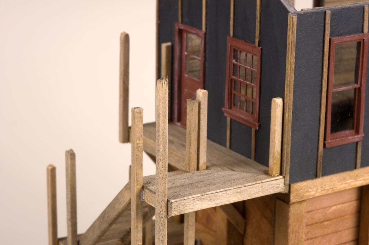 Photo 154 Corner posts for the railings were added next, four of them on the outer edge extending completely to the ground. |
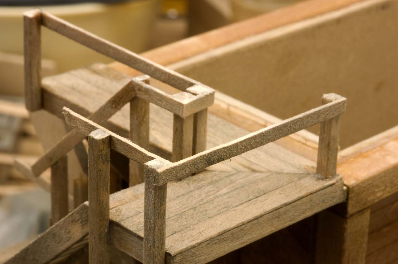 Photo 155 Horizontal and angled support boards were glued to the square posts next. | 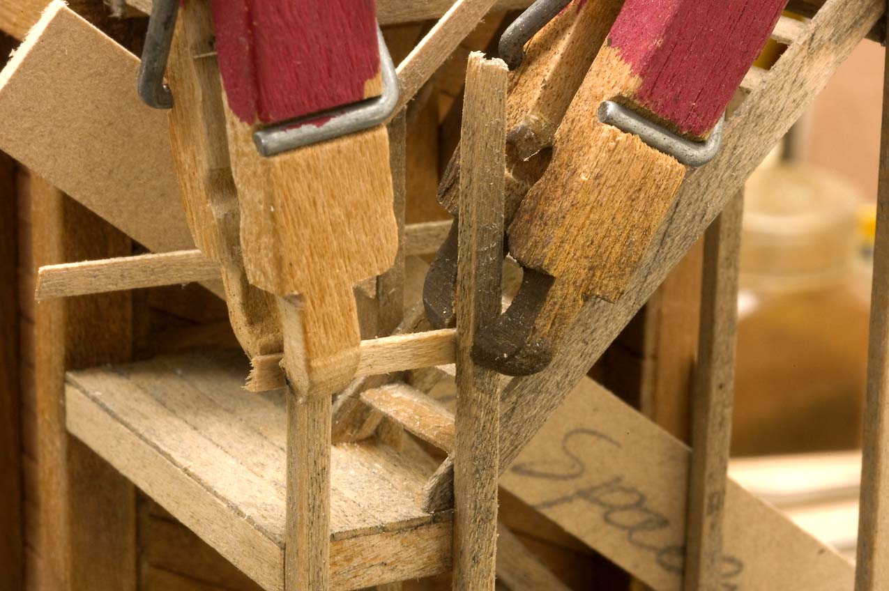 Photo 156 Clamps made by shaping the ends of ordinary wooden clothes pins were used to hold the railing pieces to the posts. |
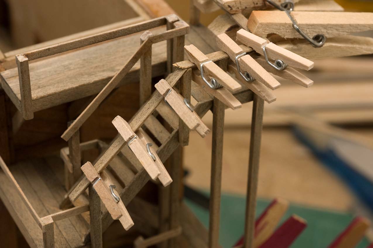 Photo 157 Many regular clothes pins were used to hold the hand rail pieces in place while the glue set. | 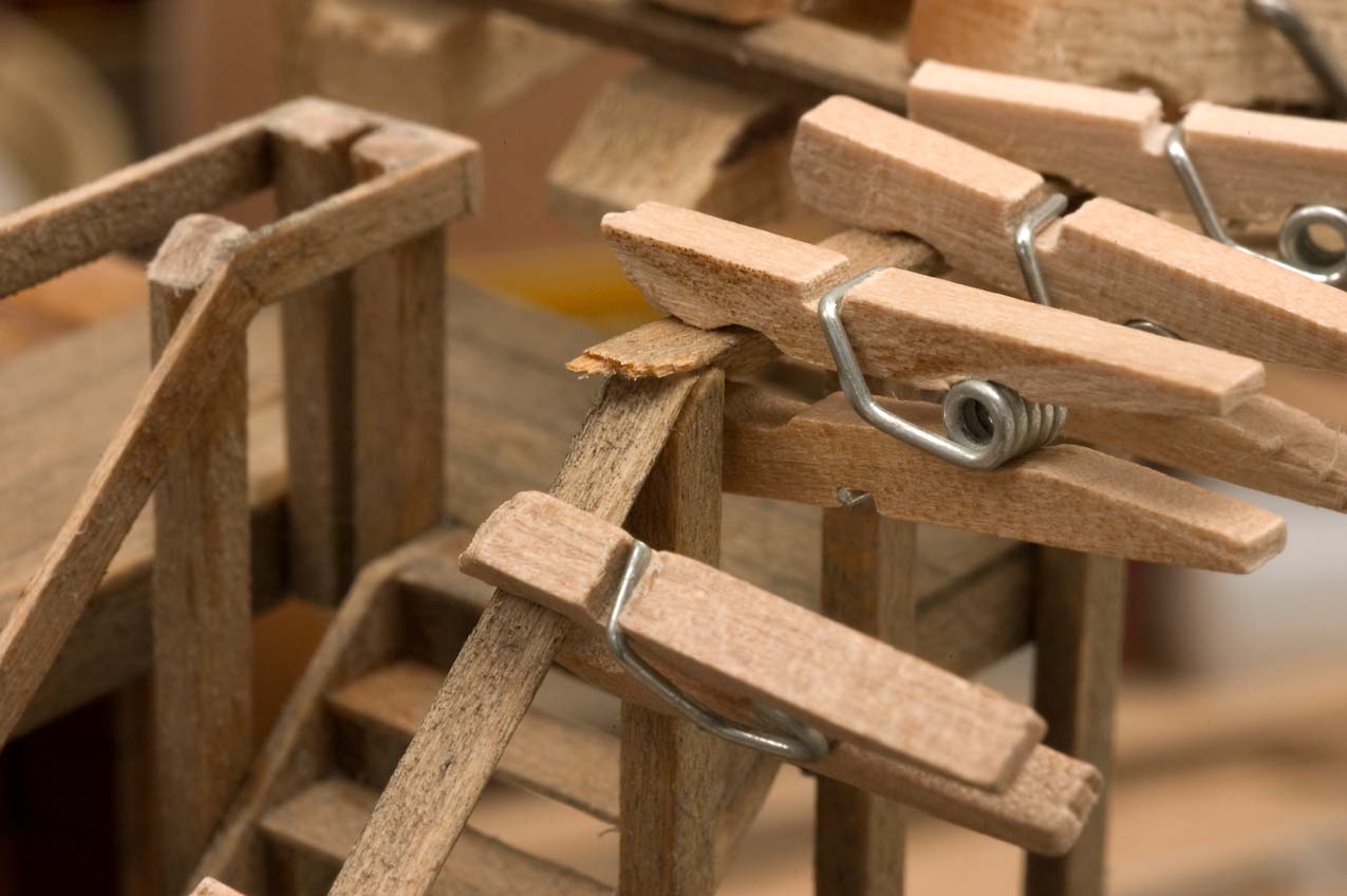 Photo 158 I wasn't too careful attaching the horizontal railing pieces. The material that extended over the angled railing was eventually sanded to a square end. |
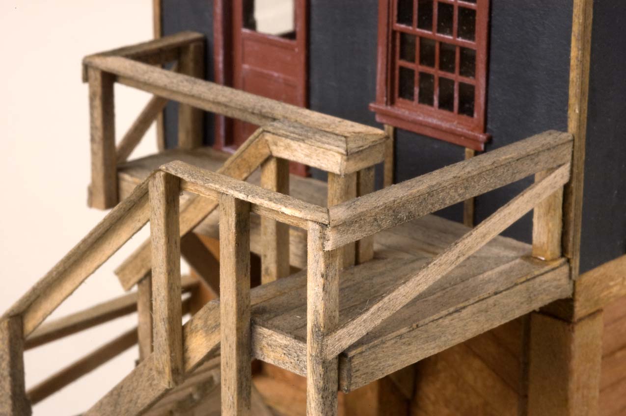 Photo 159 Additional diagonal positioned boards were added at the ends of the landings for strength and also to prevent miners from falling through to the ground. | 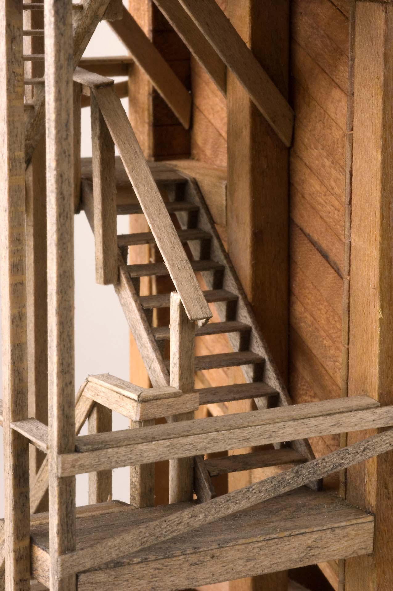 Photo 160 This is a finished view of the stairway. All the railings and braces are in place. |
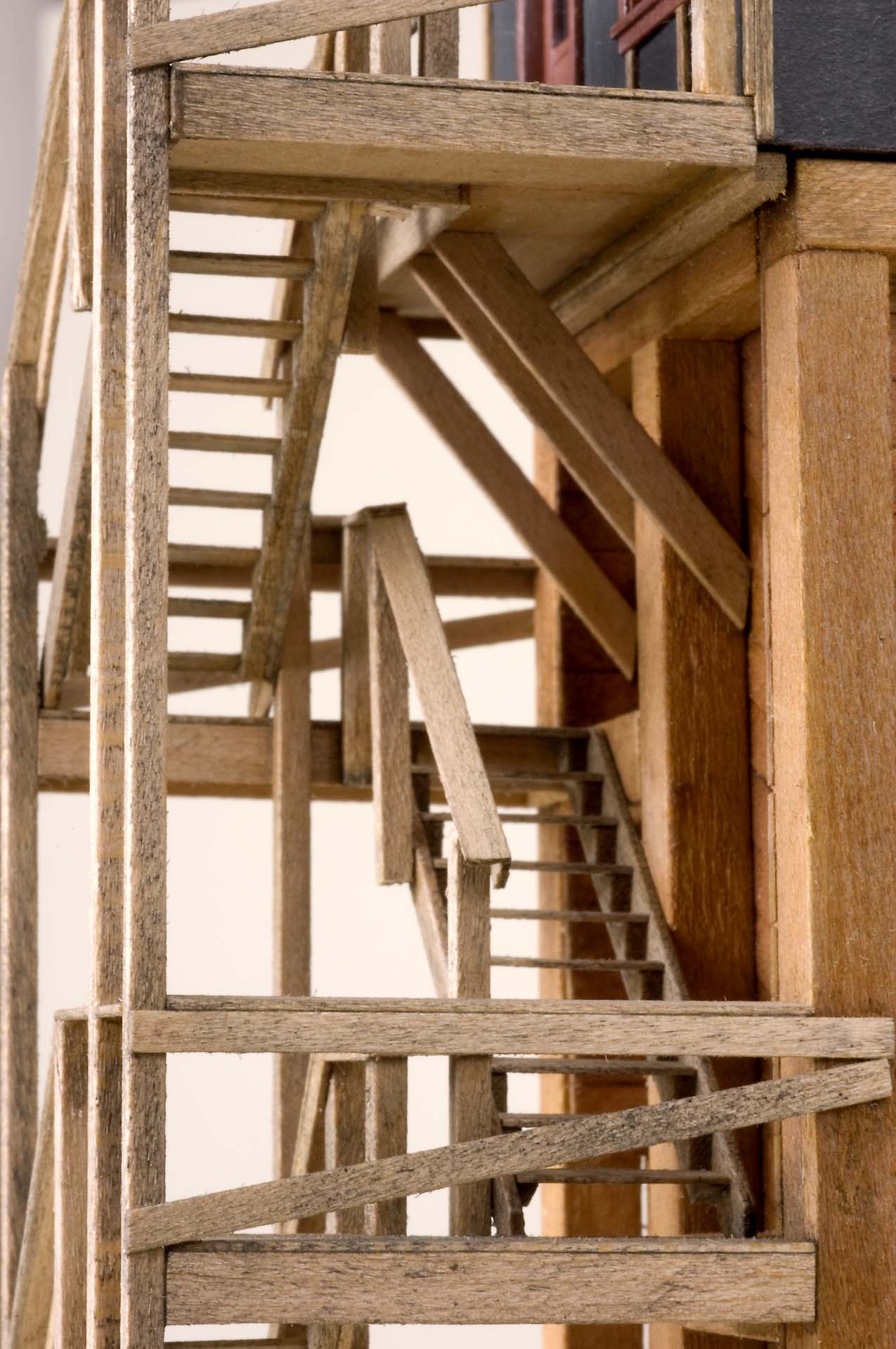 Photo 161 Here's another view of the finished stairway. All that's missing are miners going to or coming from the mine. | 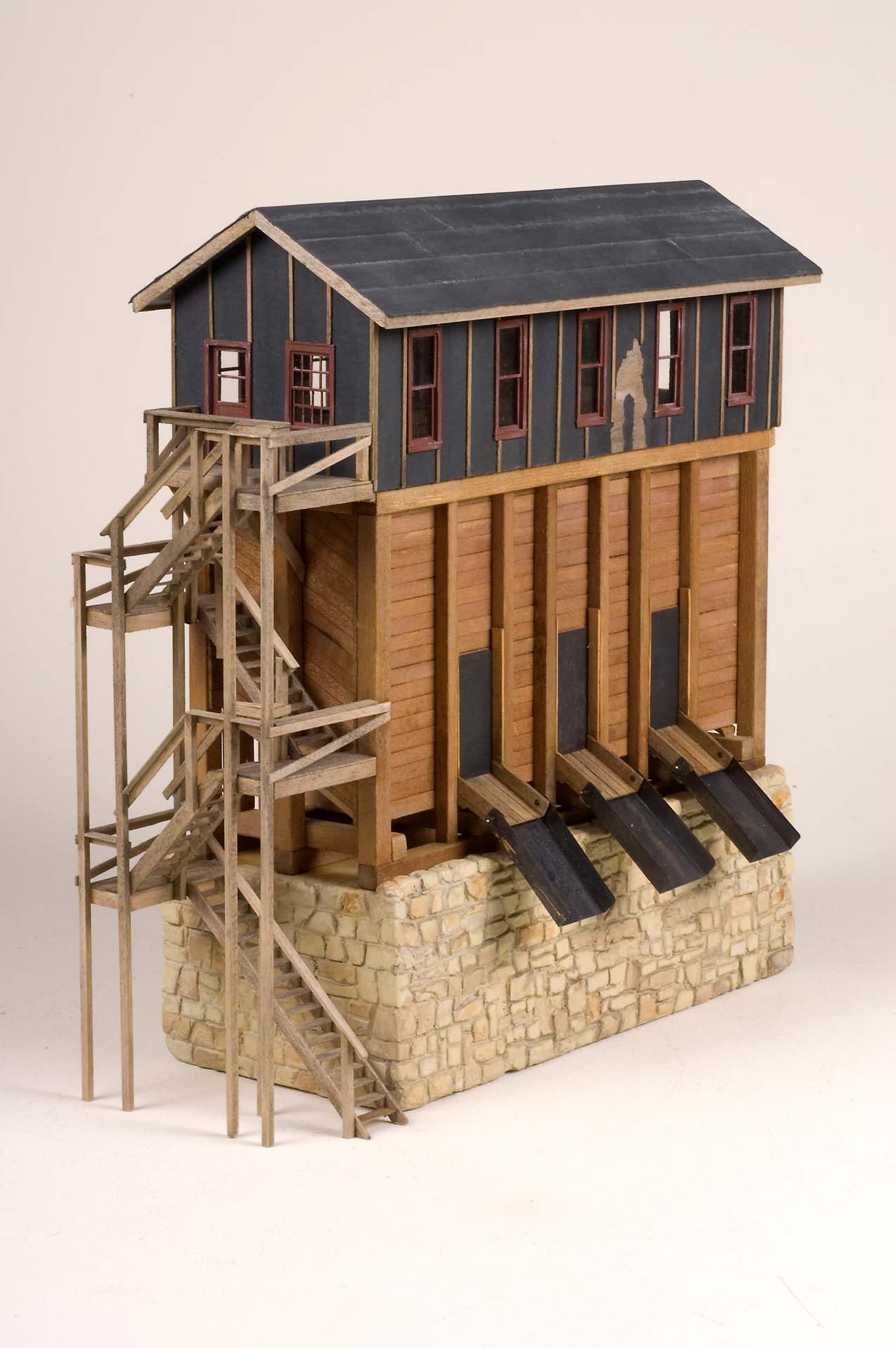 Photo 162 Here's a view of the completed stairway. Note that the three metal movable chute extensions have been reinstalled at this time. They will be permanently secured to their respective wooden chutes next. |
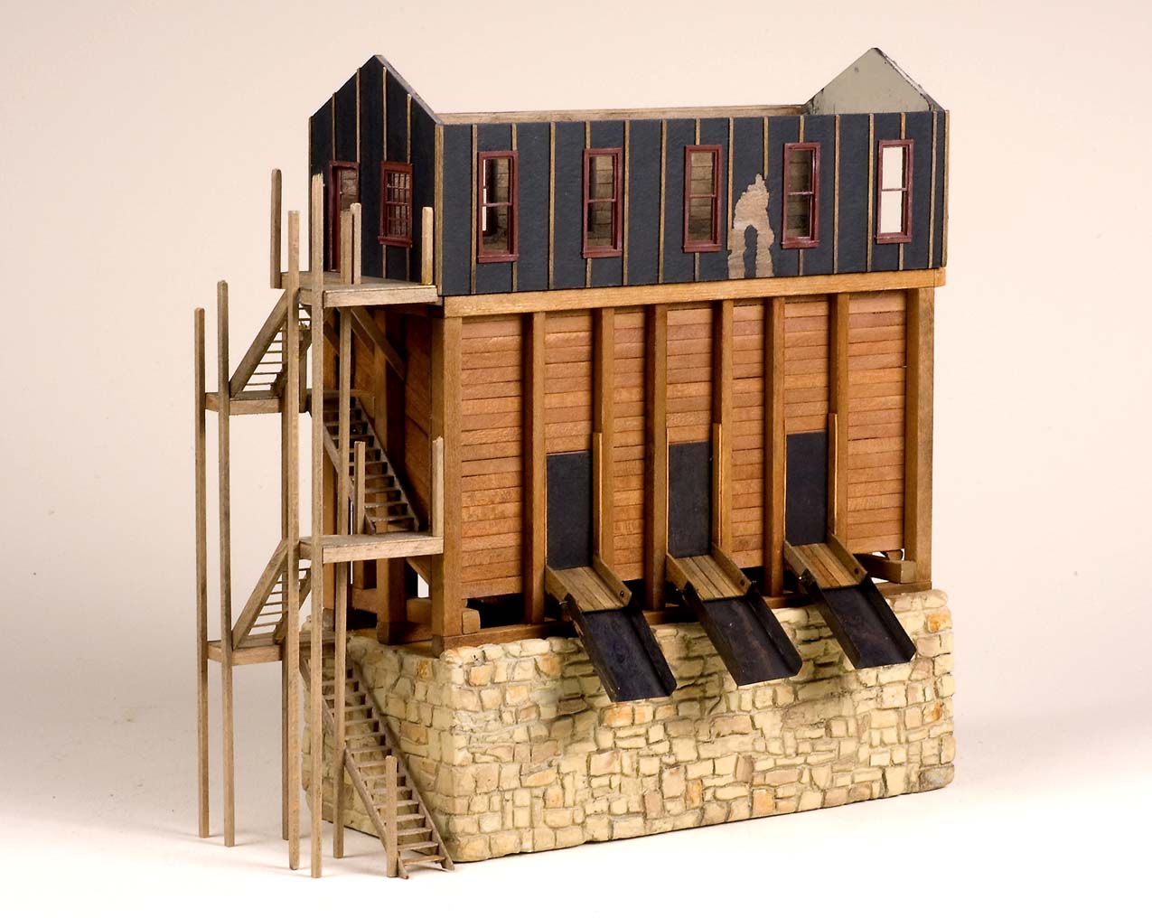 Photo 163 This view shows the three bunker doors and movable chute extensions. Like the doors, the extensions were made from thin brass shim stock. The flat headed jewelry pins have been clipped short and serve as pivot points. Rack and pinion gears mechanism details need to be added to the doors as well as lengths of chains to the chutes to restrict their downward angle. When the chutes are extended, they will safely clear the high side gondolas but not any of the K-36 or 37 locomotives that would be used at the ore bin. | 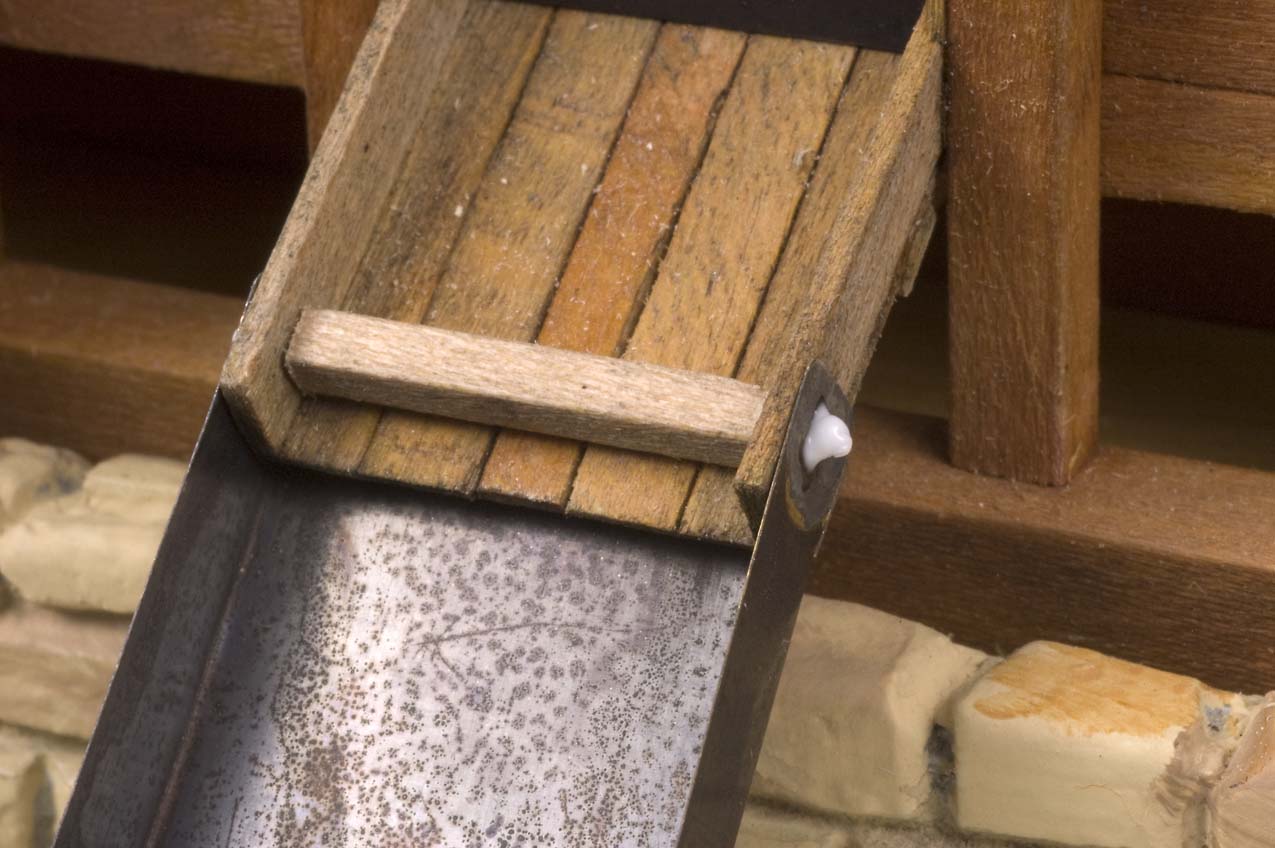 Photo 164 A small amount of the excess metal from the chute mounting pins was snipped off and covered with a dab of Aleene's Tacky Glue. A small piece of square stripwood was pressed between the heads of the mounting pins to keep them tight against the inside surface of the wooden chute sides. |
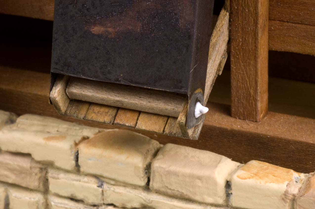 Photo 165 This view shows that even though the tacky glue is still wet, the metal chute can be moved around the mounting pin. | 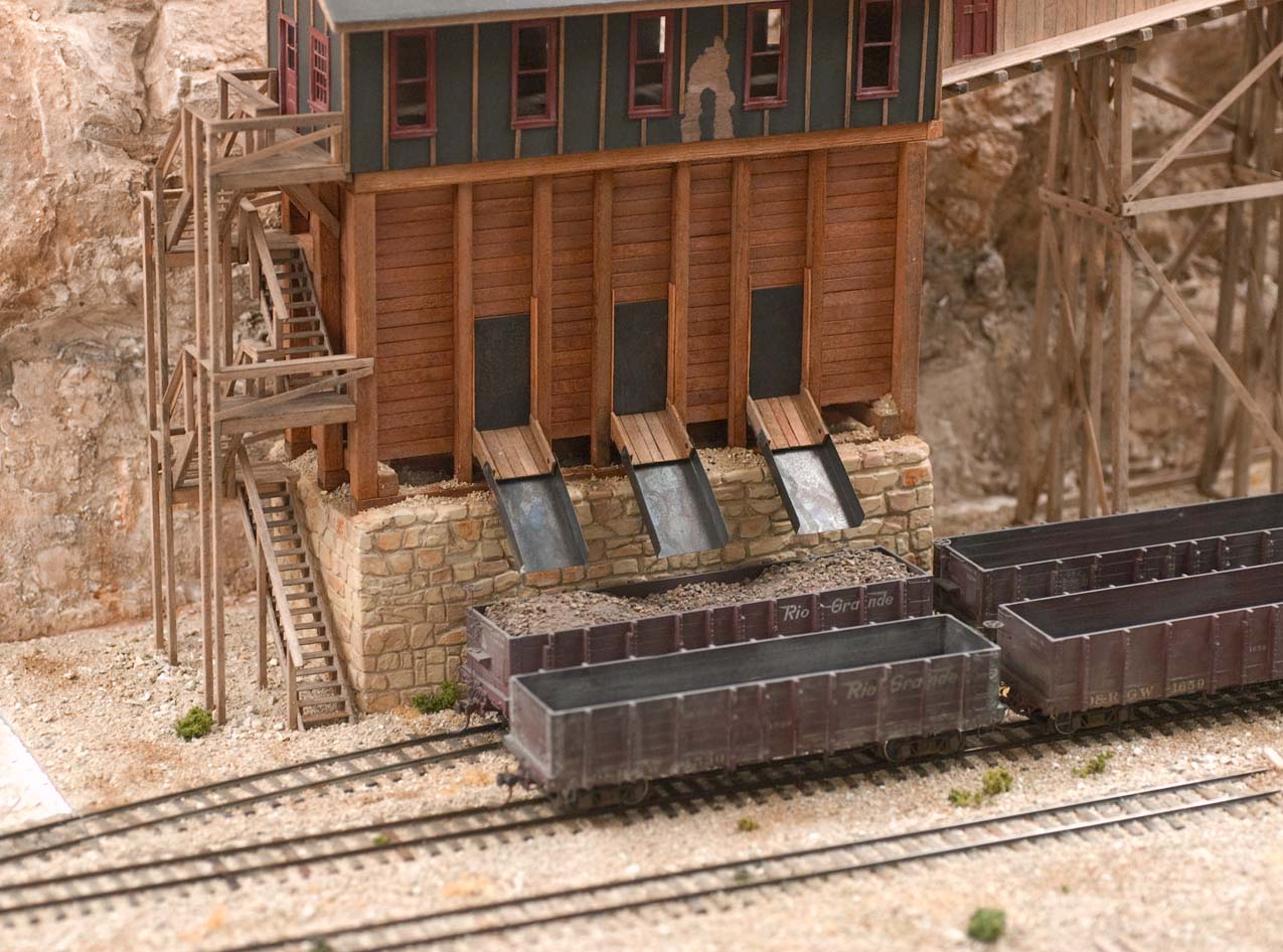 Photo 166 A few high side gondolas have been spotted on the bunker tracks. Bunker workers will be able to load each car from either one or all of the chutes at the same time without having to move the car during loading. |
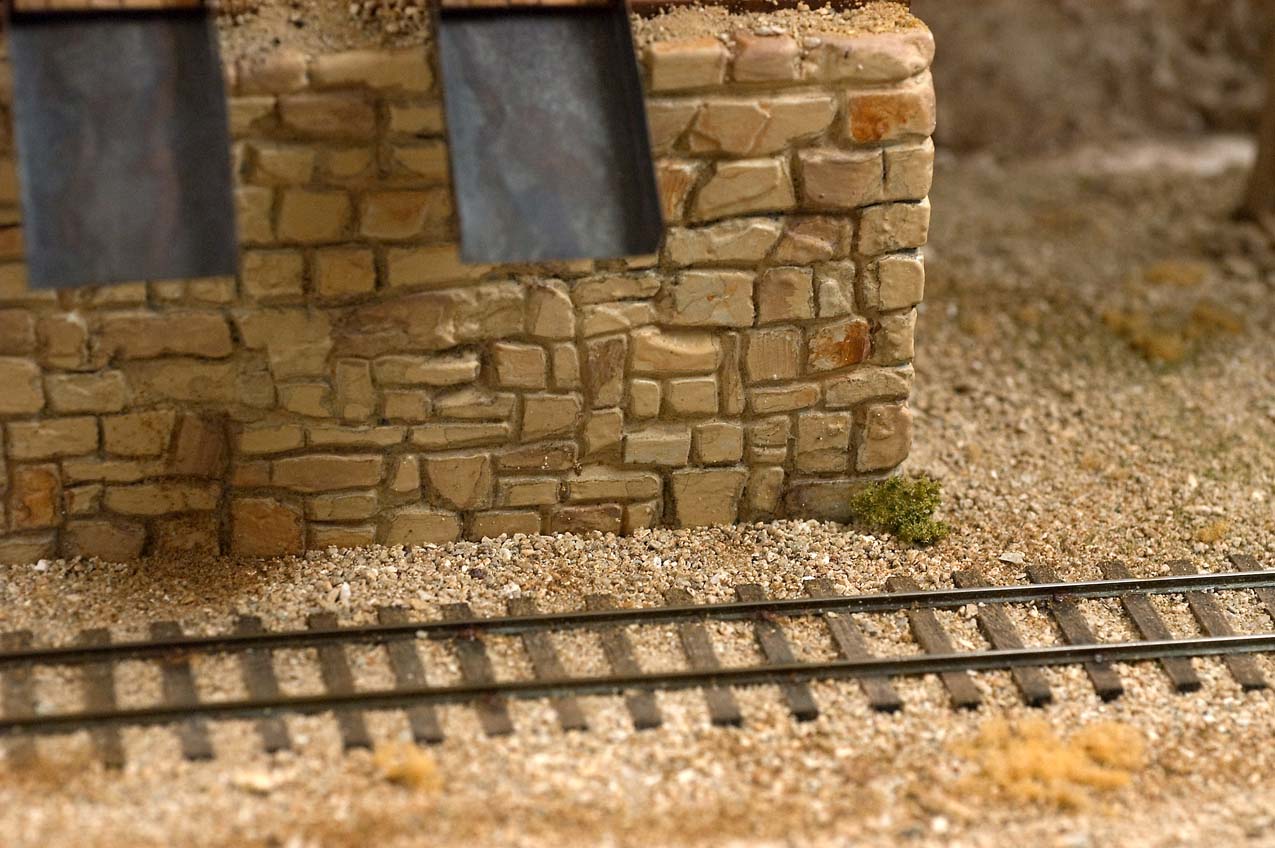 Photo 167 Limestone granules have been glued in place around the stone base of the bunker. Ground foam and clusters have been added but more scenic materials and mining debris still needs to be glued in place. | 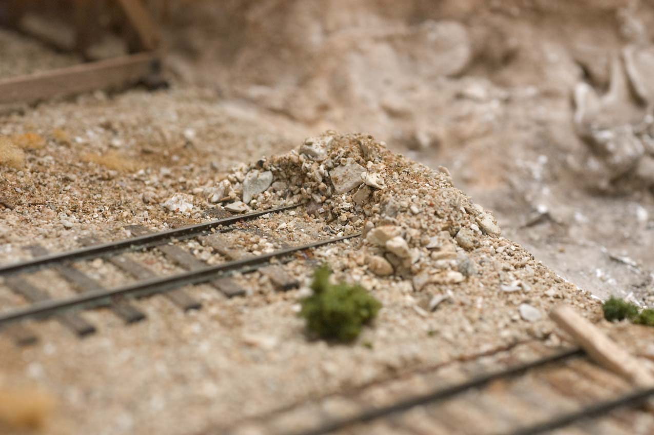 Photo 168 A couple of varieties of wheel stops have been employed at the end of the loading spurs. This one is simply a pile of ballast with a small depression to clear the Kadee uncoupling lever. |
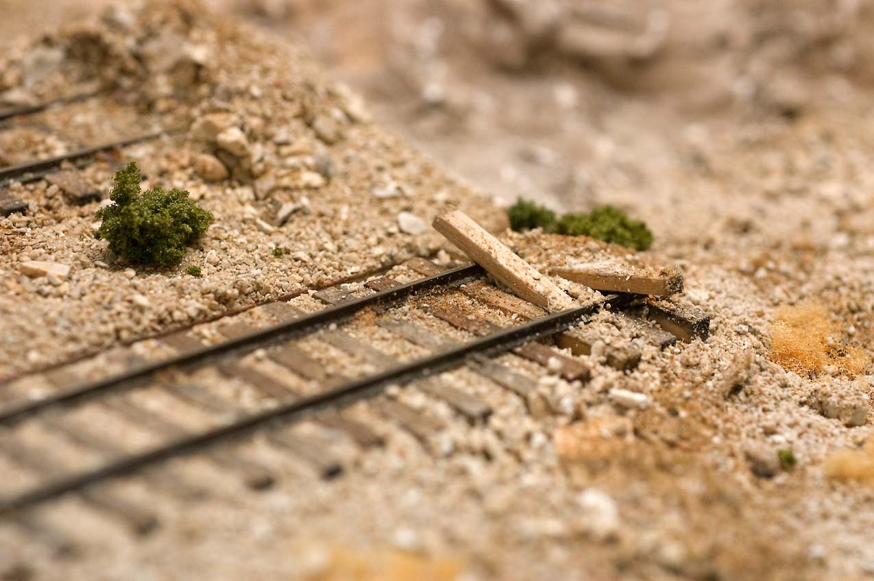 Photo 169 In this case, two diagonally placed ties have been wedged below the rails. Again, they were positioned to clear the Kadee uncoupling lever. | 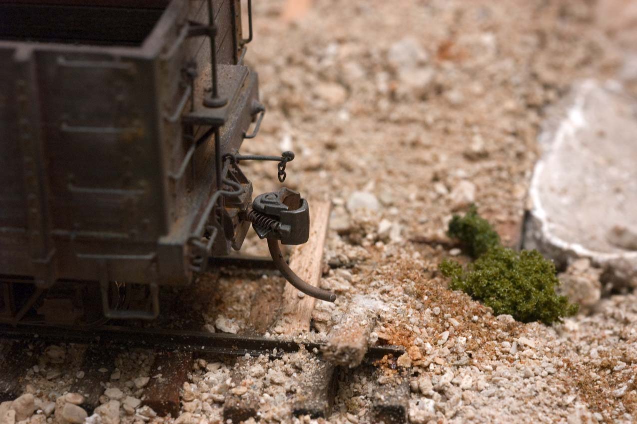 Photo 170 This close up view shows the small amount of clearance between the angled tie wheel stops and the Kadee uncoupling lever. |
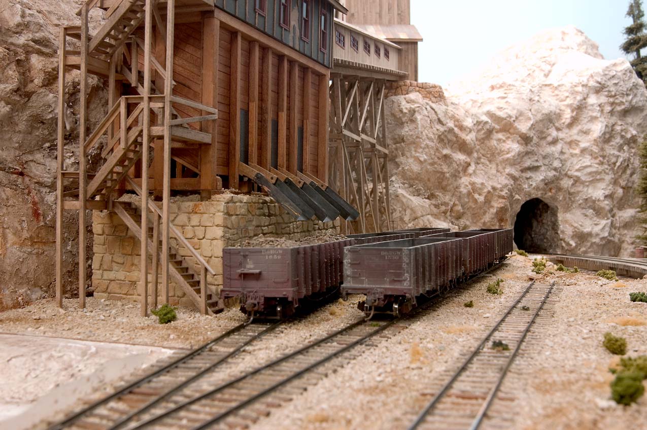 Photo 171 Things are starting to look like a mine in this scene. Three cars are on the loading track and three more are on the waiting track. A local switcher, either a C-19 or the #50 diesel move the cars in and out of the two bunker spur tracks. | 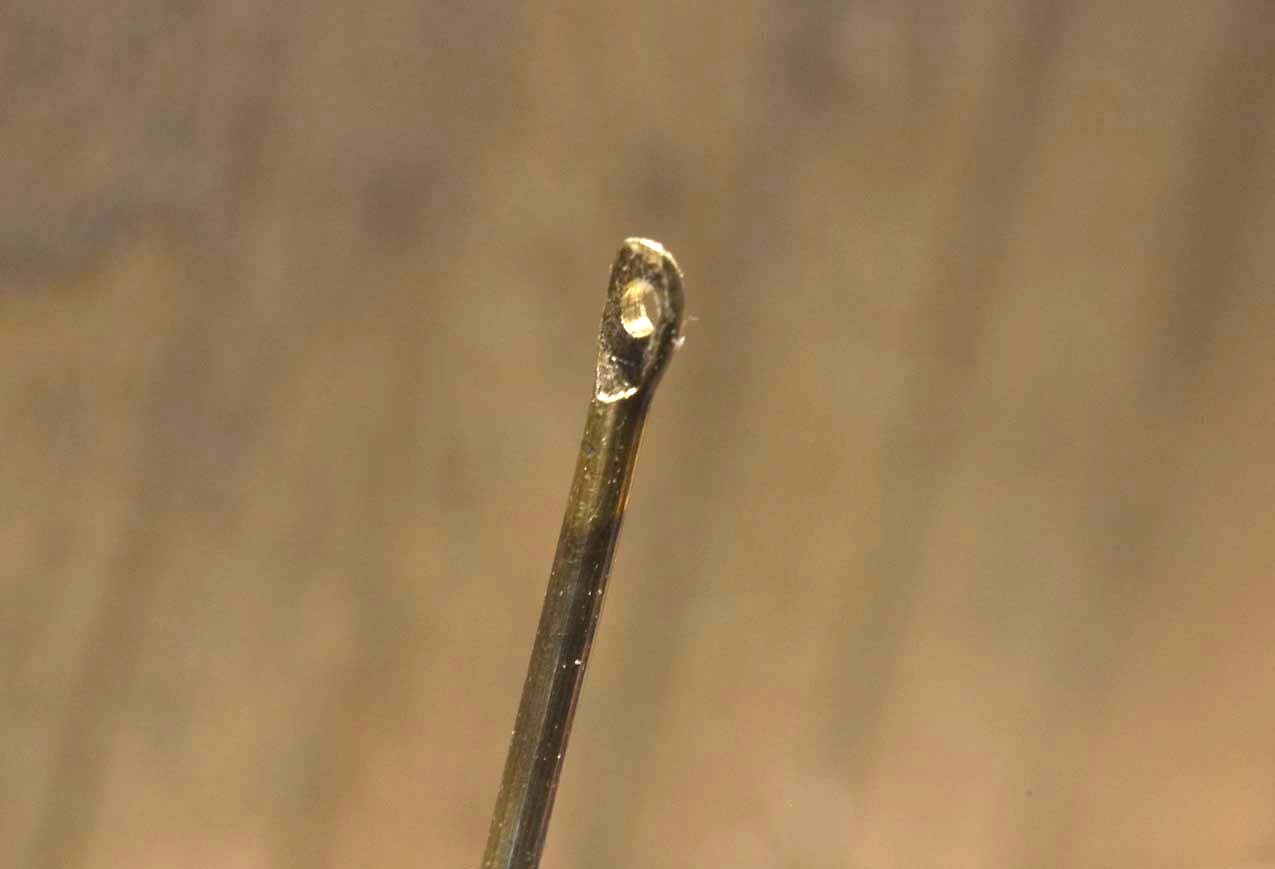 Photo 172 About all that's left now is to add some interesting, yet important details. This close up is of a piece of .025" brass wire that had it's end heated with a small flame, then squeezed in the jaws of a machinist vice. |
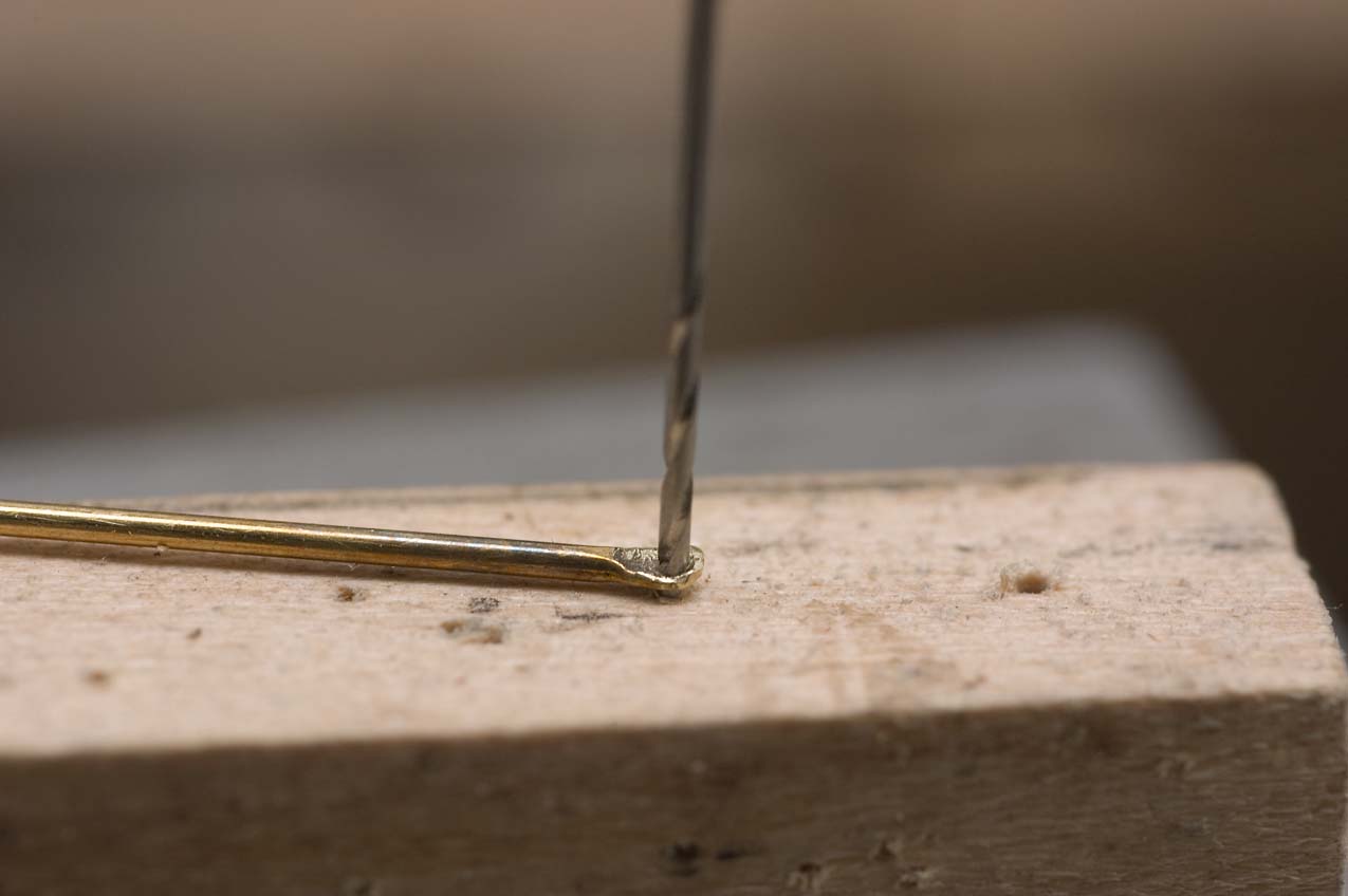 Photo 173 The wire was held with a pair of pliers while a #78 drill is being used to drill a hole through it. | 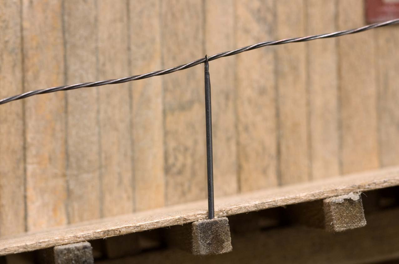 Photo 174 Prior to being installed into a hole drilled in to one of the walkway support timbers, the wire was chemically blackened with Gun Bluing solution |
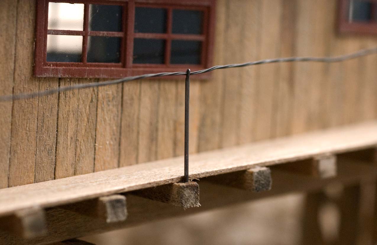 Photo 175 Three strands of extremely fine multi-strand wire were also chemically blackened and when dry were threaded through the holes drilled in the vertical stanchions. | 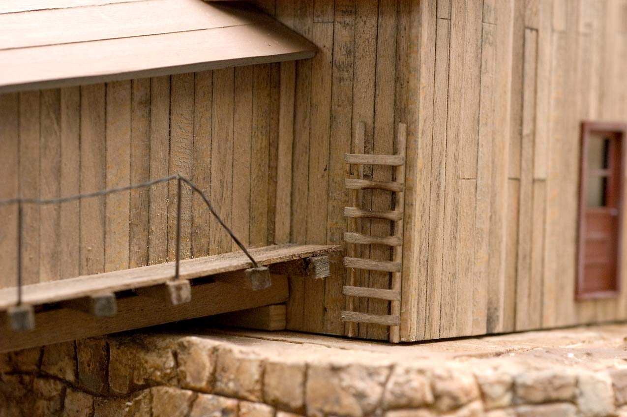 Photo 176 The wire was extended downward through a hole drilled in one of the square timbers. Note the darkened hand grabs on the small ladder on the wall of the mine. To represent years of hands grabbing the rungs, I thought charring them with a match would create the worn effect. The more I look at the ladder, it looks like it was on fire at one time. |
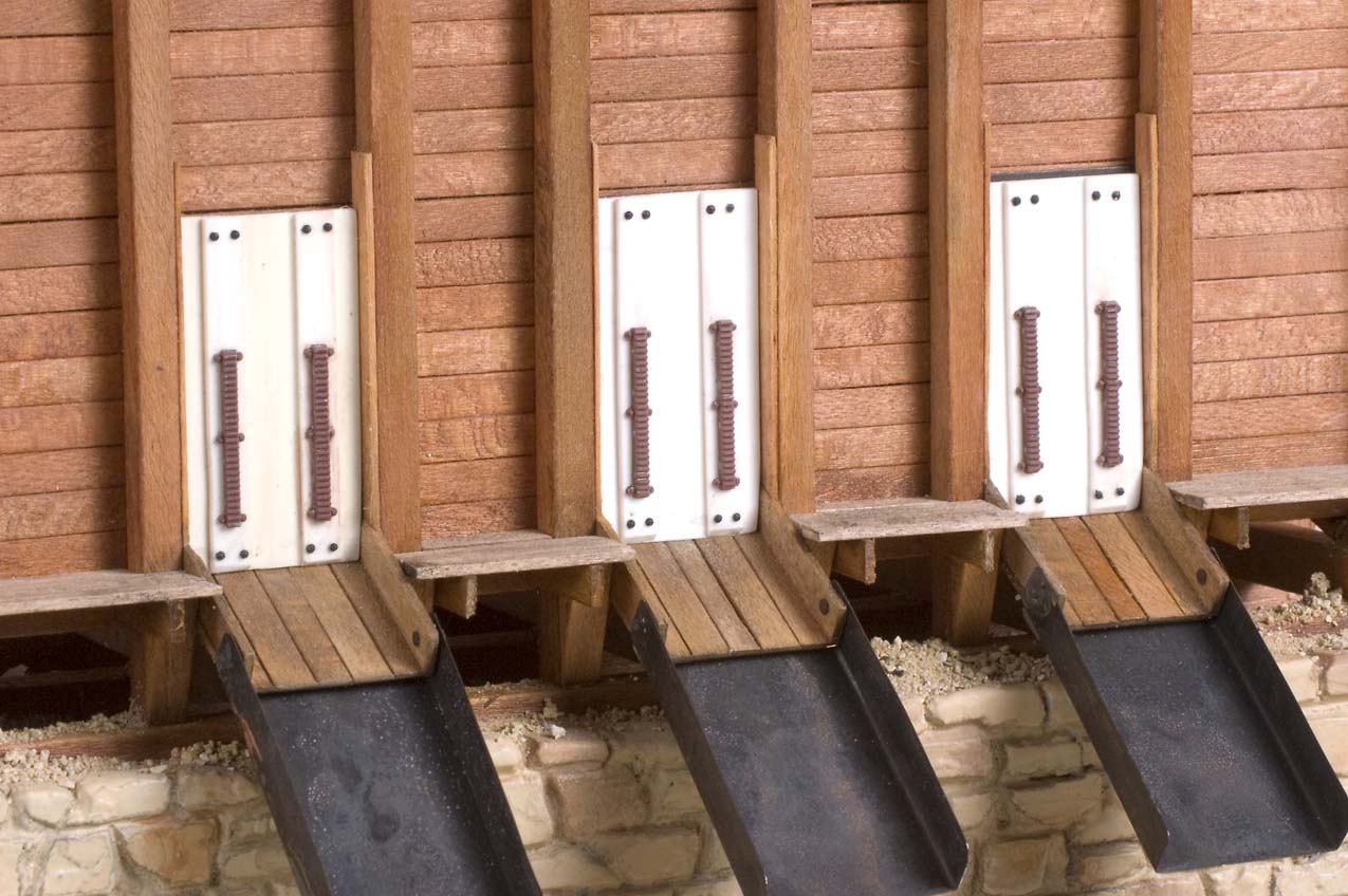 Photo 177 The rack and pinion detail components came from Raggs...to Riches. | 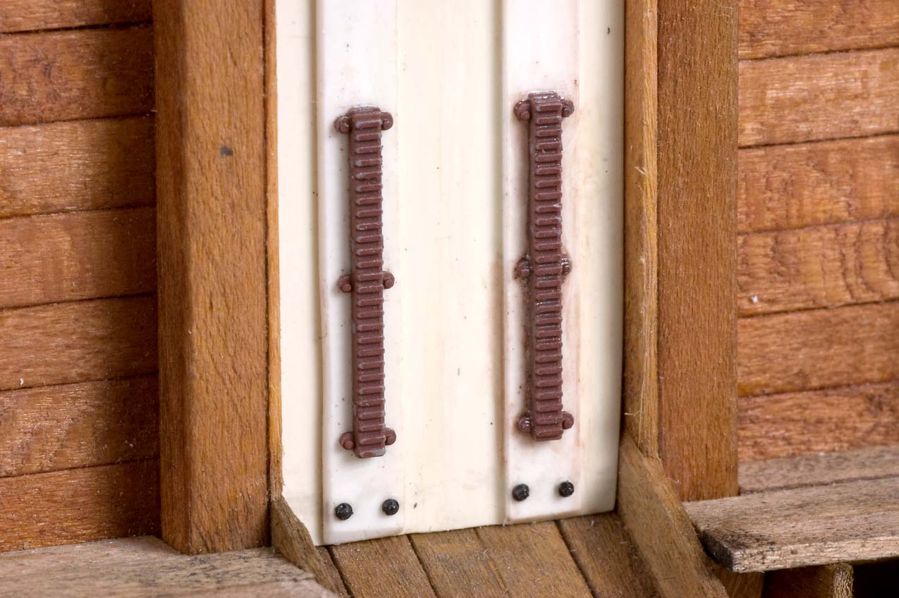 Photo 178 A thin piece of white styrene was attached to the brass chute doors with double-face tape. Then two supporting pieces of styrene were added to allow the rack teeth to engage the teeth of the pinion gears. Small Grandt Line NBW castings were glued to the additional supports. |
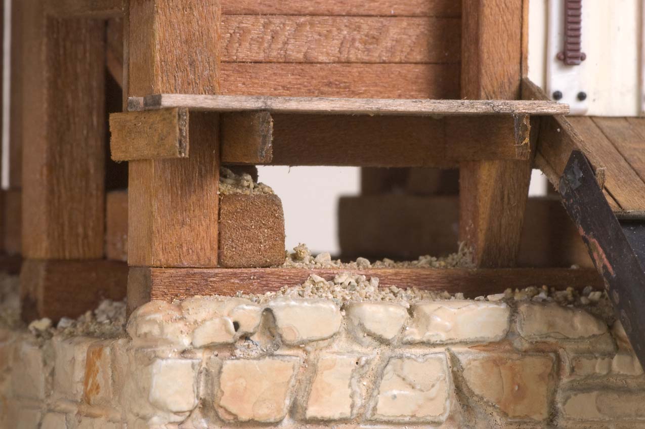 Photo 179 At this time, short horizontal braces were installed to support a two-board wide walkway for bunker chute door operators to move from chute to chute. | 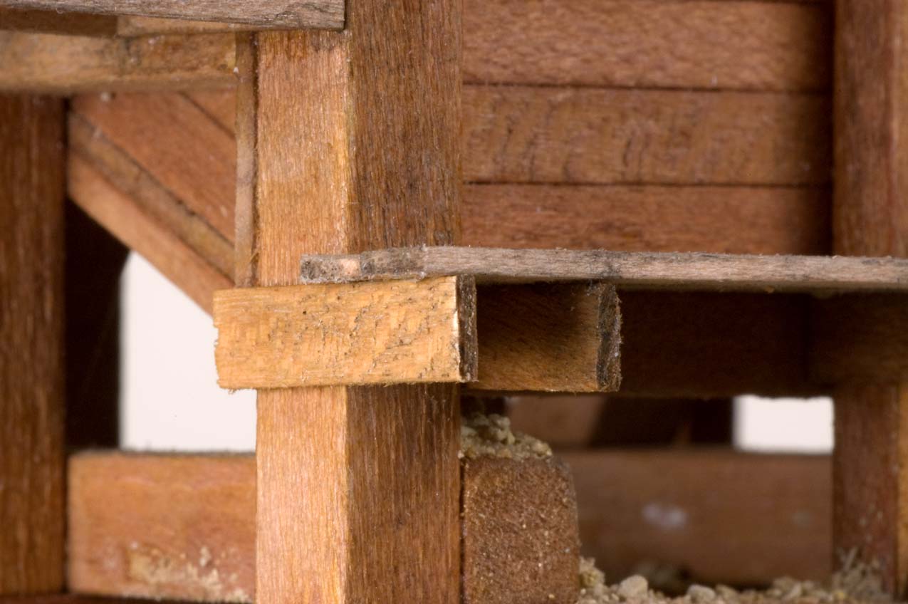 Photo 180 Here's a close-up view of the supports for the chute worker's walkway. |
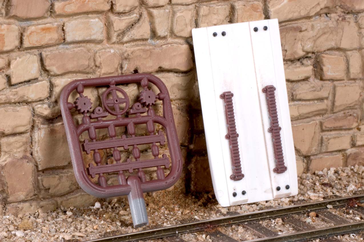 Photo 181 The rack and pinion sprues have enough parts for one set of doors. Prior to being used, the sprues were spray painted with Polly Scale, D&RGW Freight Car Red, paint,. | 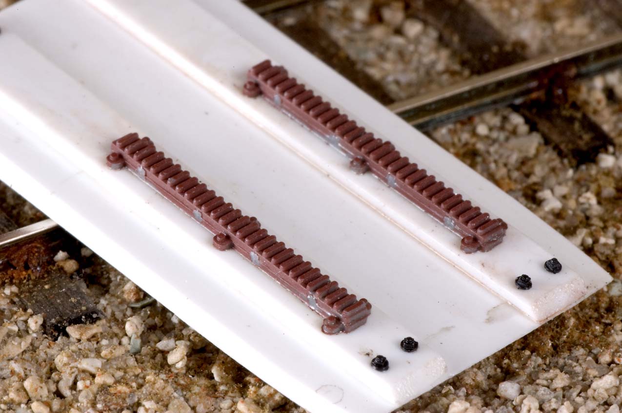 Photo 182 The paint on the rack details flecked off because of the handling while they were being glued to the styrene facing. I wasn't too concerned because the door component would be touched up with additional paint. |
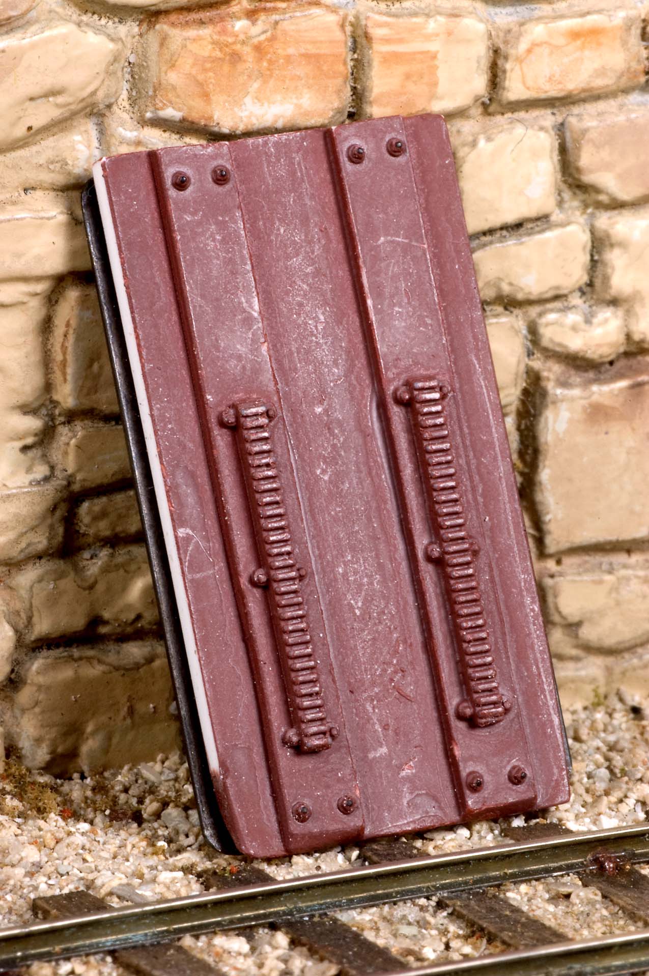 Photo 183 The panel was then attached to the brass chute door made earlier. It is visible along the left edge of the assembly. | 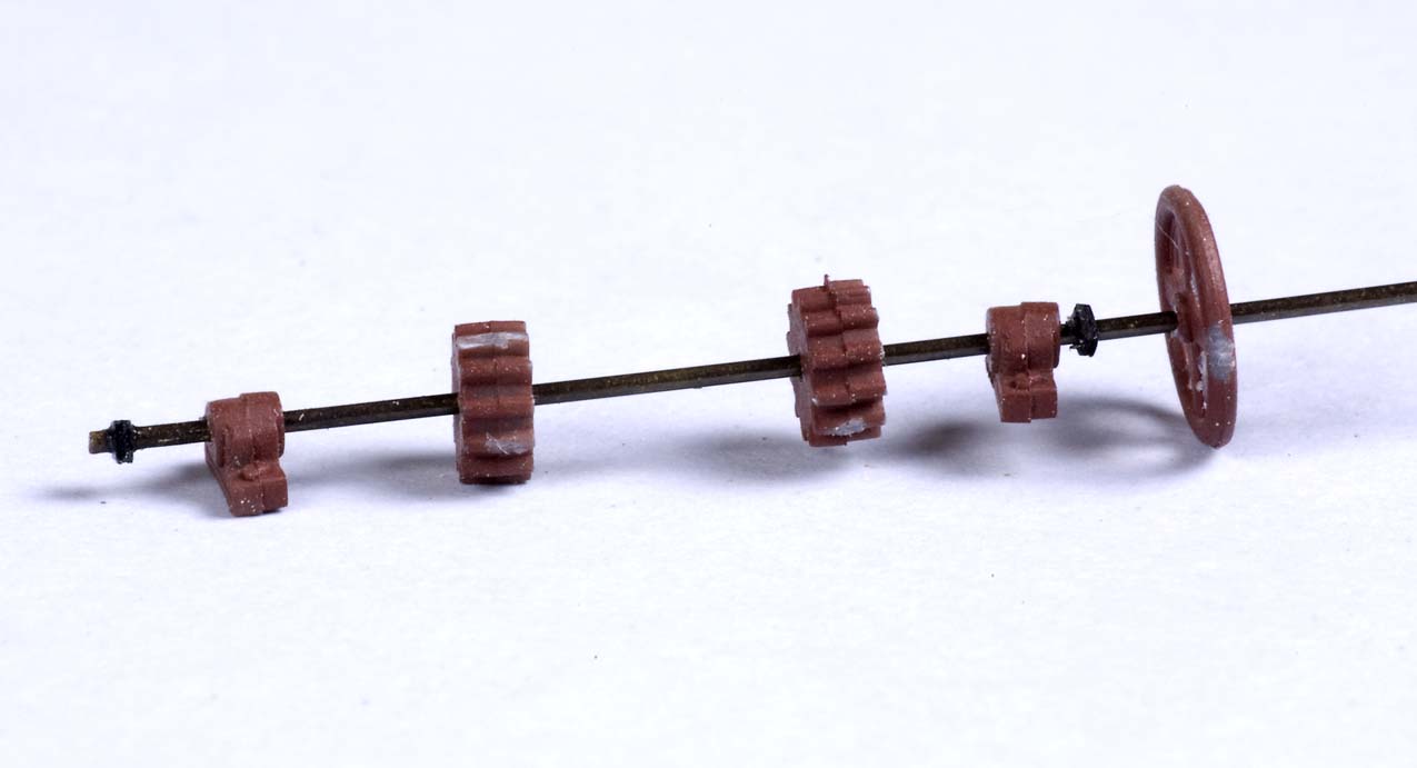 Photo 184 All the pieces for the pinion/pillow block and hand wheel assembly were drilled to clear a short piece of .020" chemically blackened brass wire, |
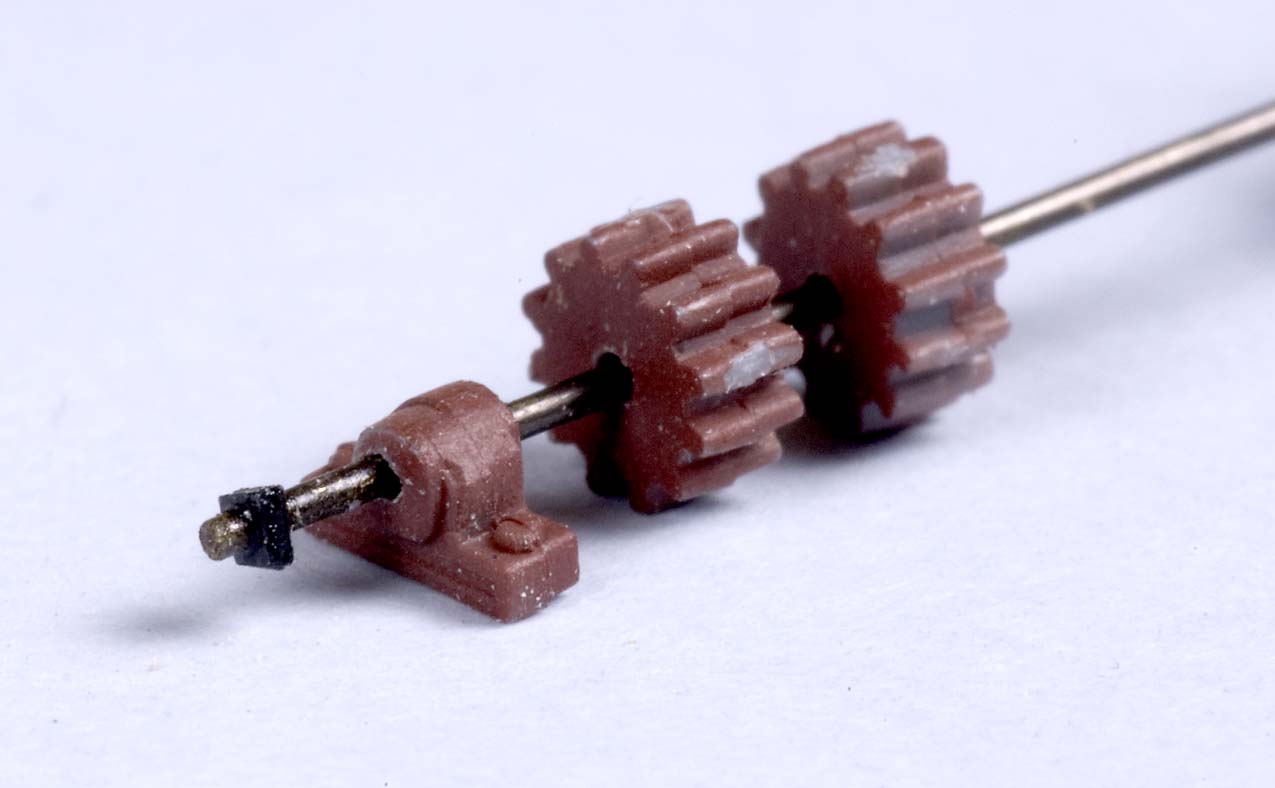 Photo 185 This view shows the addition of a square nut attached to the end of the brass rod. It was made from a thin piece of styrene. | 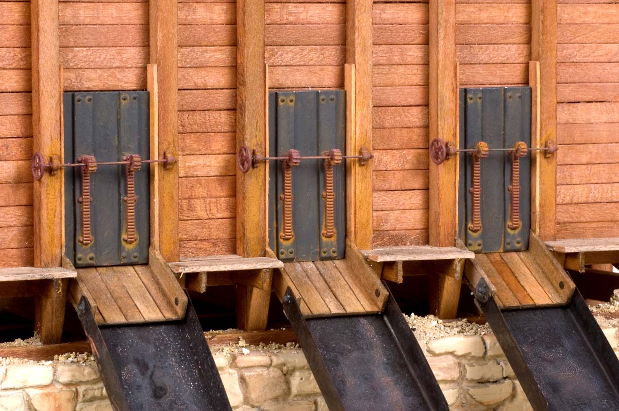 Photo 186 A scale figure was temporarily placed on the walkway to determine where the hand wheel for the pinion gears needed to be located. I decided to put it about 4.5' above the walkway. After the rod holding the gear components was firmly in place, the entire sliding door assembly was brush painted with a, "Sweet & Sour," rust solution. |
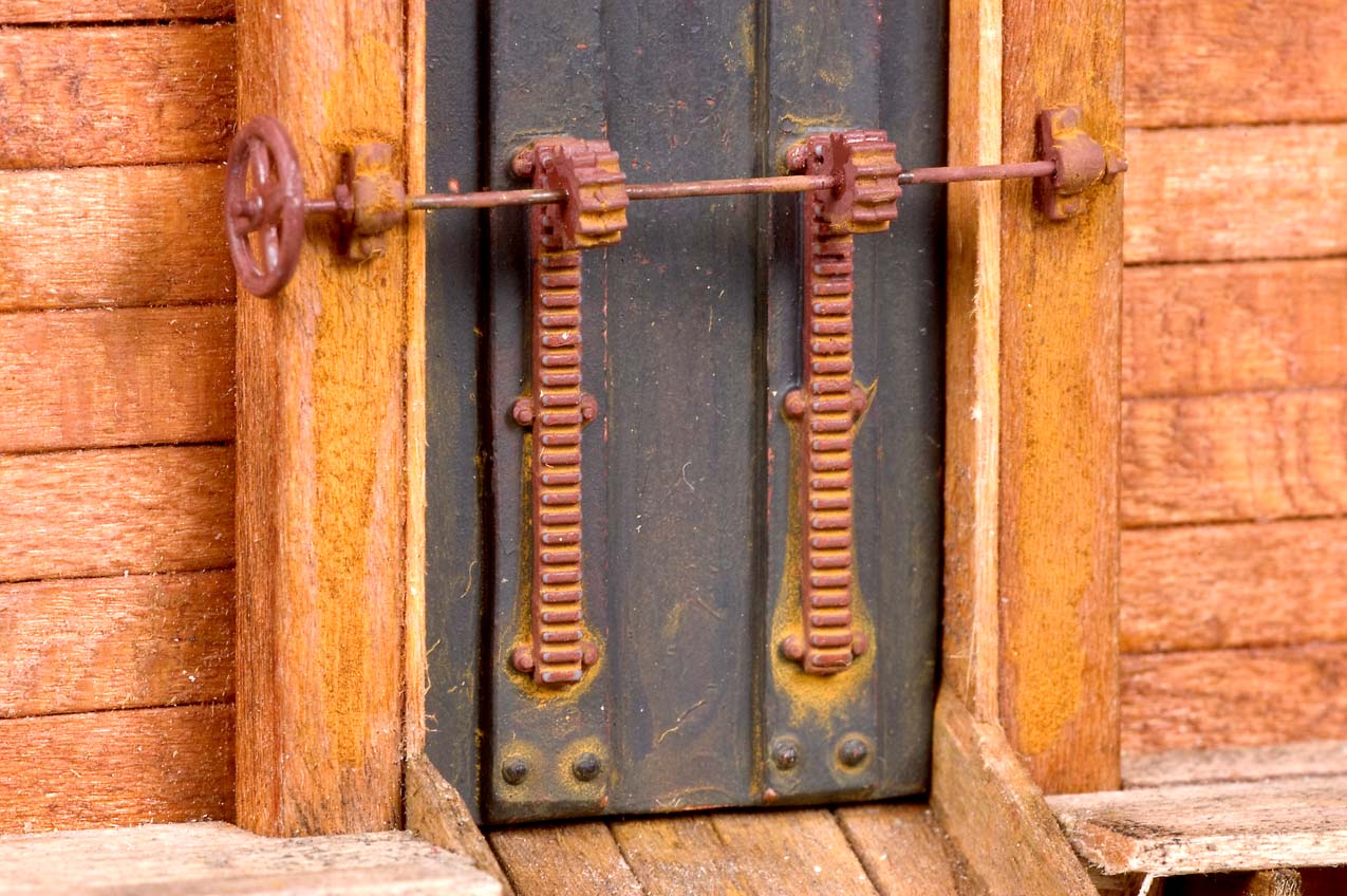 Photo 187 Here's a closer view of the movable door panel after it was given a washing with the rust solution. |  Photo 188 The chute doors are complete doors with their rack and pinion opening mechanism details installed and weathered with the rust solution. |
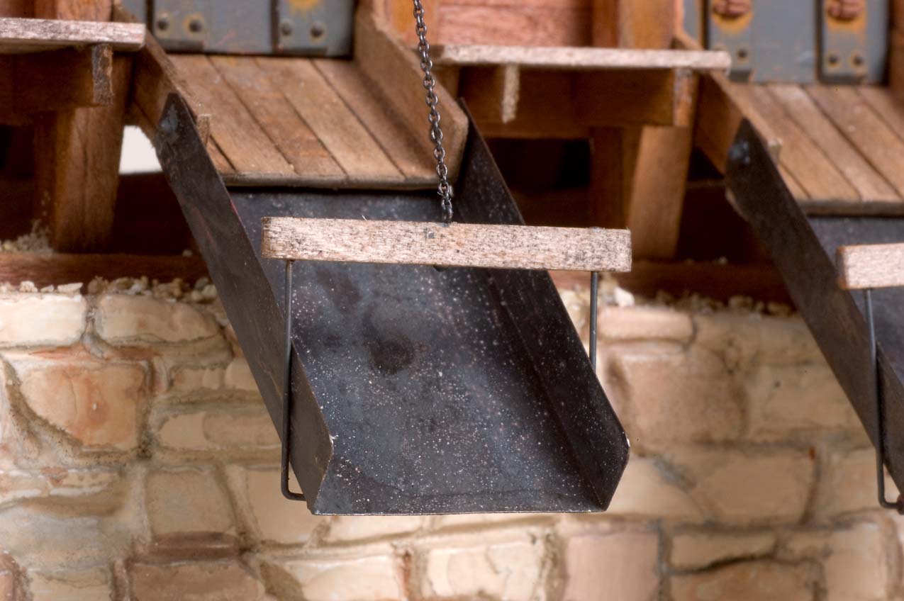 Photo 189 Lifting yokes or brackets for the metal chute extensions were fashioned from a length of .020" brass wire, a piece of stripwood and some styrene scraps. | 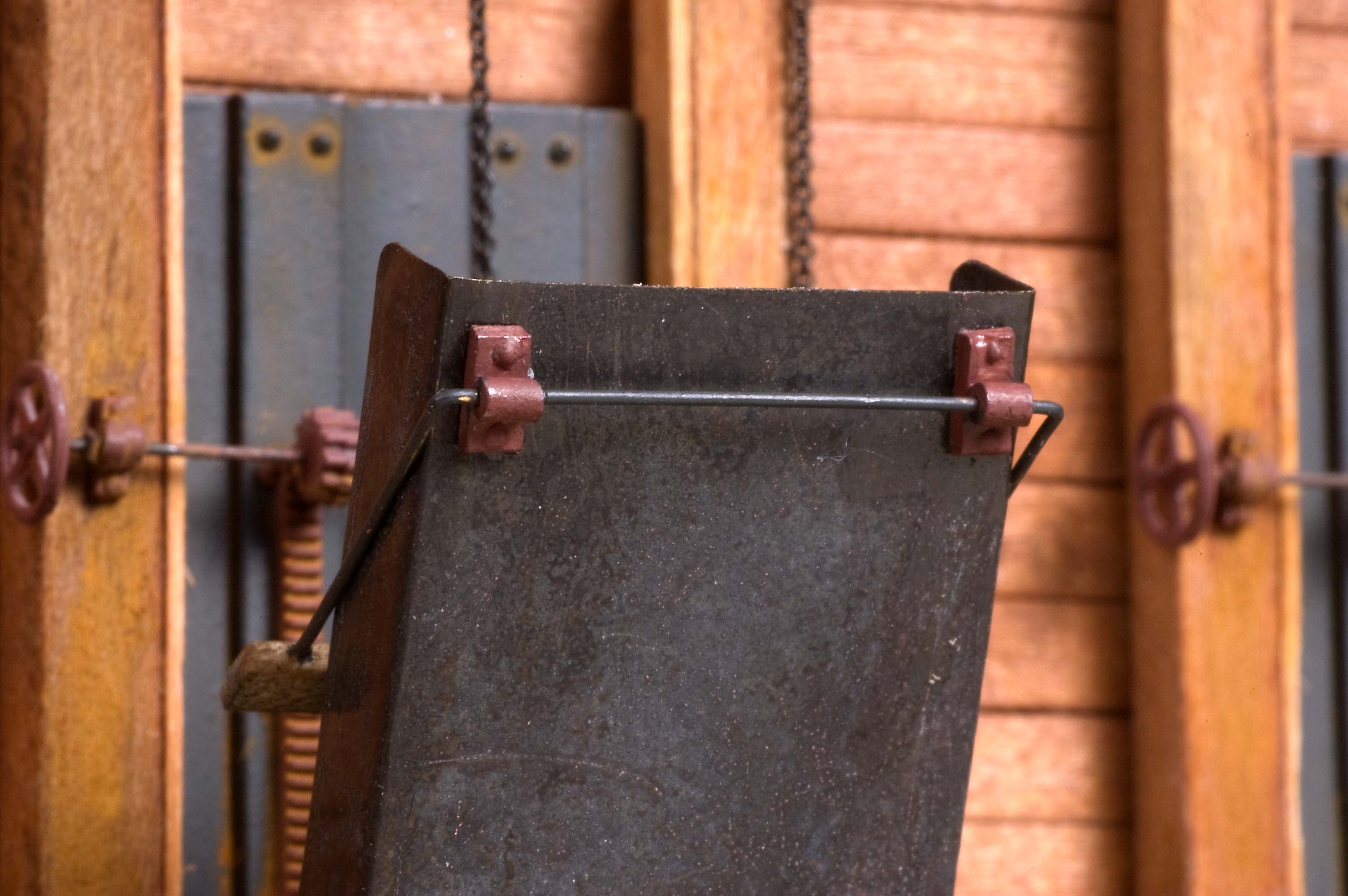 Photo 190 The underside of the chute lifting yoke includes two wire guides made from short lengths of styrene tubing and scrap. The rivet head details are really tiny dots of the Aleene's Tacky Glue. The idea to use glue to create the rivet heads came from professional model builder, Matt Dillow. |
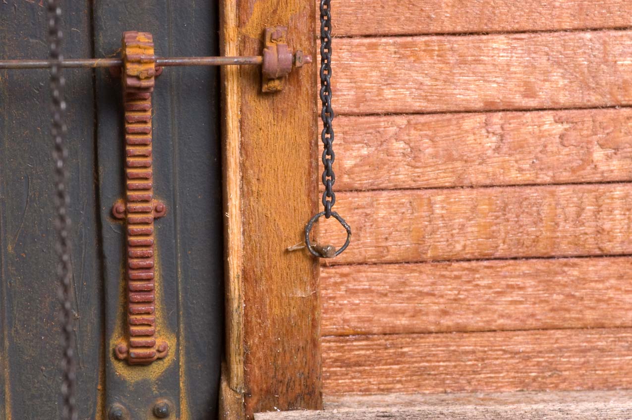 Photo 191 An end ring, made from a piece of .008" brass wire was formed and slipped through the end link of the chain and it's wire ends soldered together. The ring offers a hand-hold for the bunker laborer to raise the chute gate by pulling the chain. A small brad was provided to keep the ring in place when the chute was closed. | 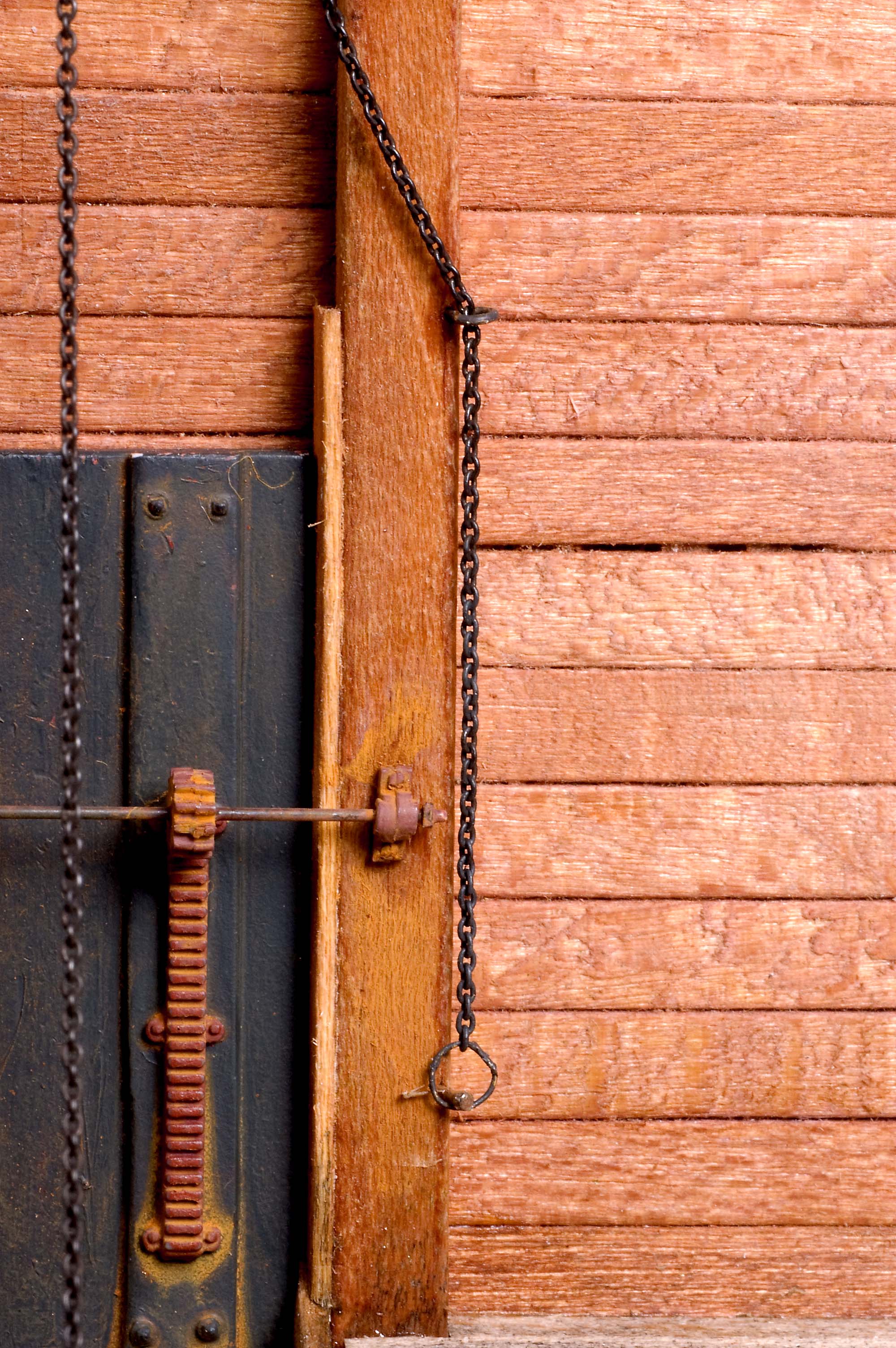 Photo 192 Tiny brass eyelets were formed and press into drilled holes to guide the chain to a point above and centered on each chute door. |
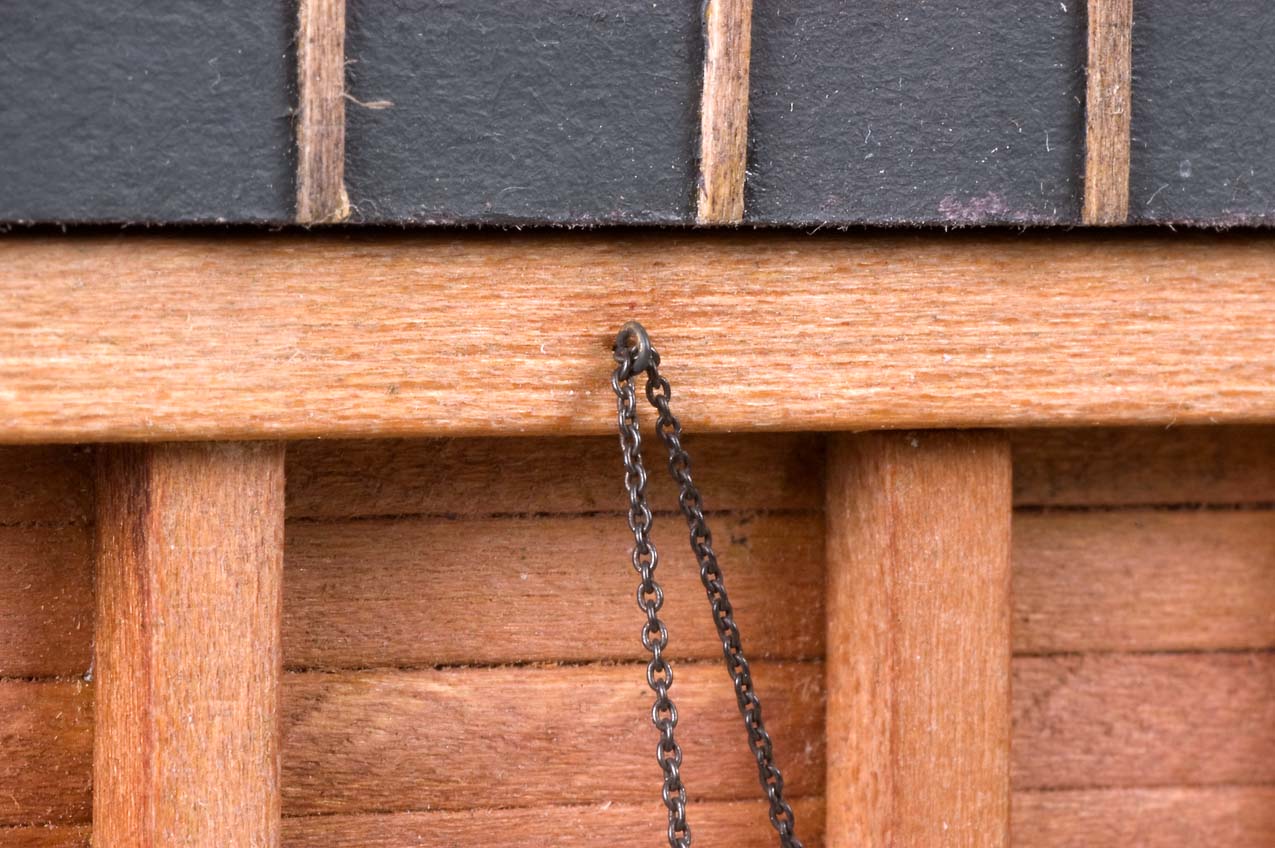 Photo 193 From this eyelet at the top of the bunker, the chain was routed down to the chute lifting yoke. | 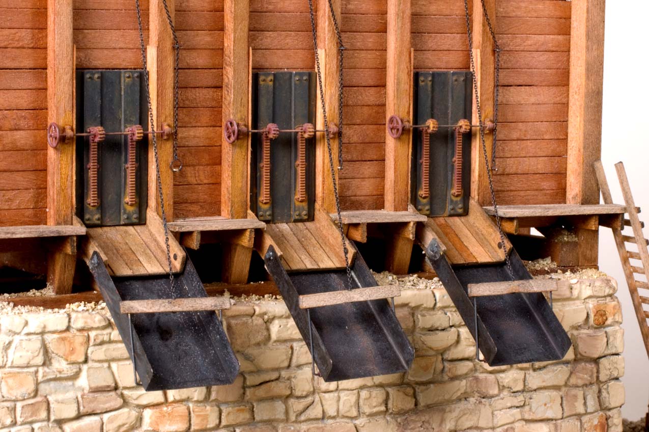 Photo 194 All three chutes are in their down and ready to load positions. chute gate and lifting |
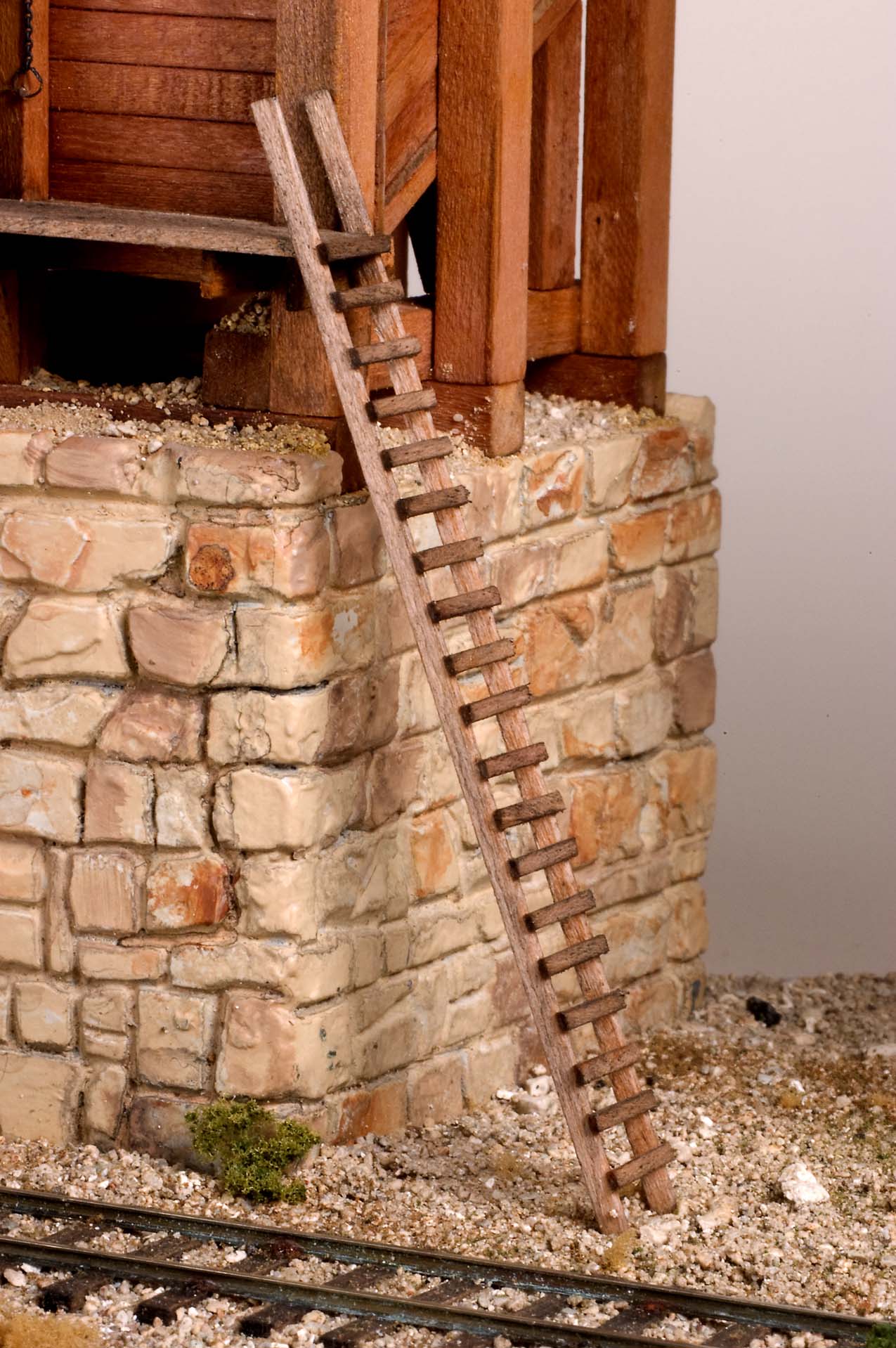 Photo 195 This long wooden step ladder was built with thin stripwood in an assembly fixture and when ready, glued in place against the mine end of the bunker stone base. | 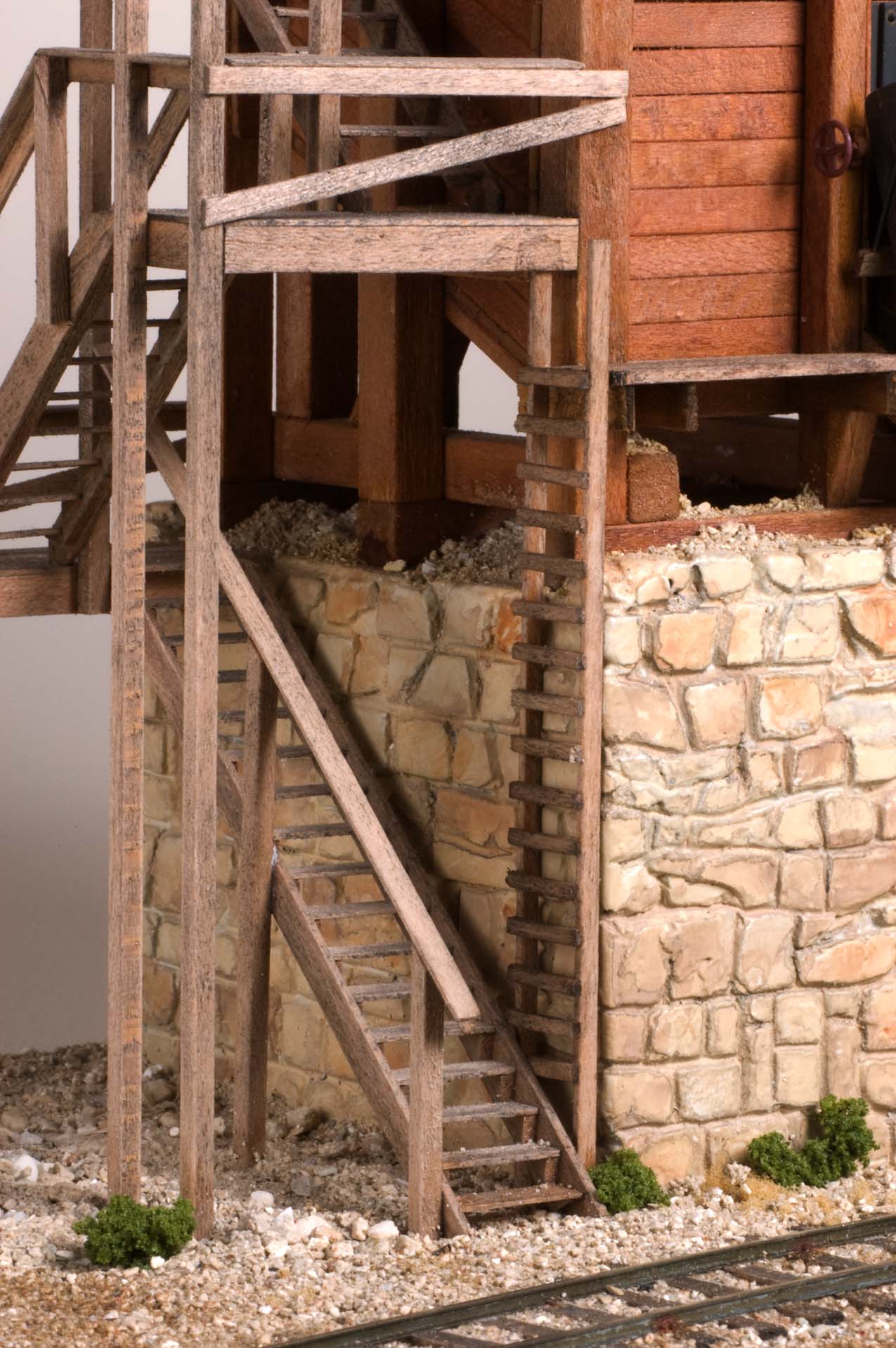 Photo 196 Another step ladder was built and attached to the stone base at the stairway end of the bunker. These ladders make it easy for the laborers to reach the loading chute platform. |
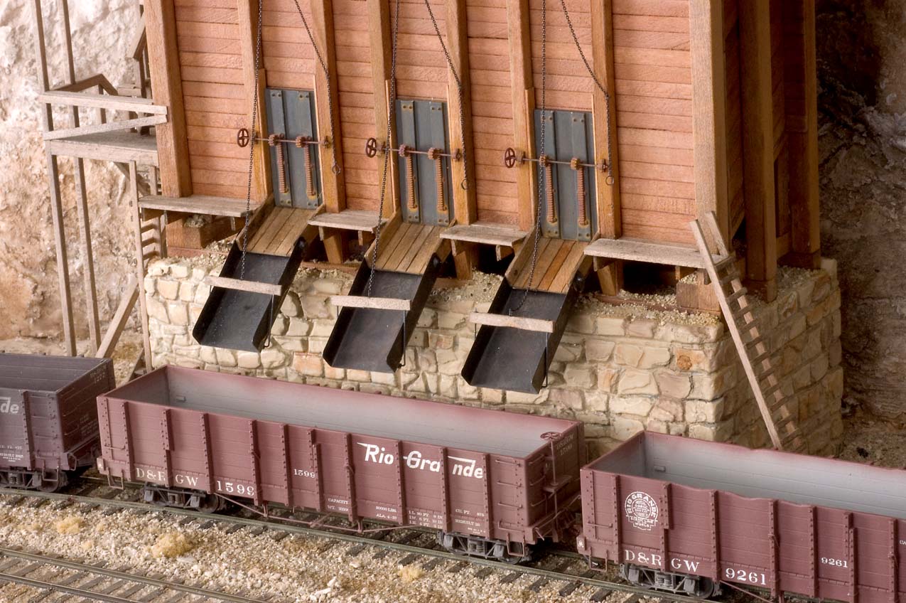 Photo 197 These empty high side gondolas are being spotted on the loading track and positioned under the chutes. | 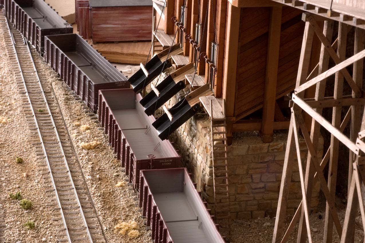 Photo 198 After three gons are placed on the loading track, the other three will be spotted on the bunker ready track. |
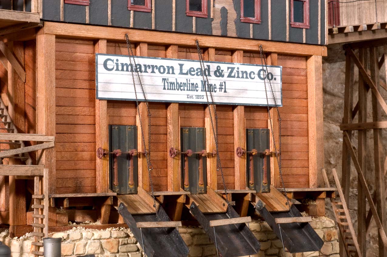 Photo 199 A large sign board for the mine bunker was created on a computer using Photo Shop Elements software. The printed sign was then sprayed with matte fixative and glued to a small piece of 1/64" aircraft plywood. When the glue was dry, the plywood was trimmed to the sign borders and tack glued to the bunker timbers with a few dots of the Tacky Glue. | 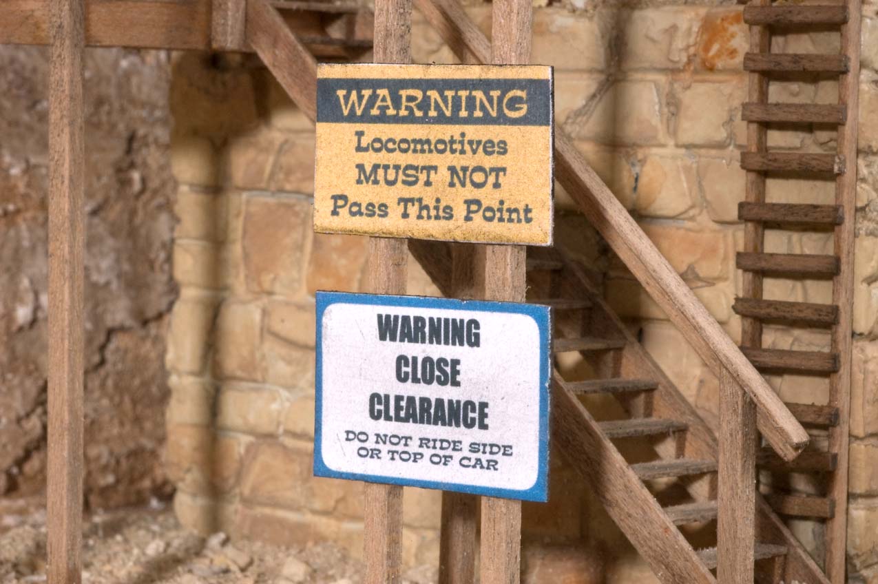 Photo 200 Additional warning signs were made in similar fashion and glued to a couple of the stairway support timbers. The large K-36 and K-37 engines used at the mine will not clear the metal chute extensions when they are lowered for car loading. |
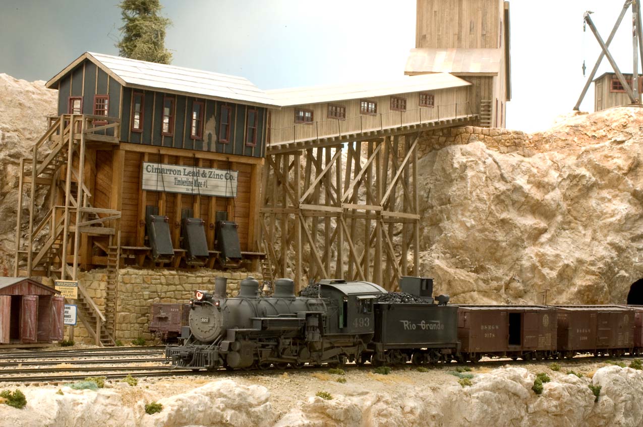 Photo 201 D&RGW #493 is seen pulling a string of box cars past the mine on its way to make deliveries to the other mines of the Silverking Mining District. | 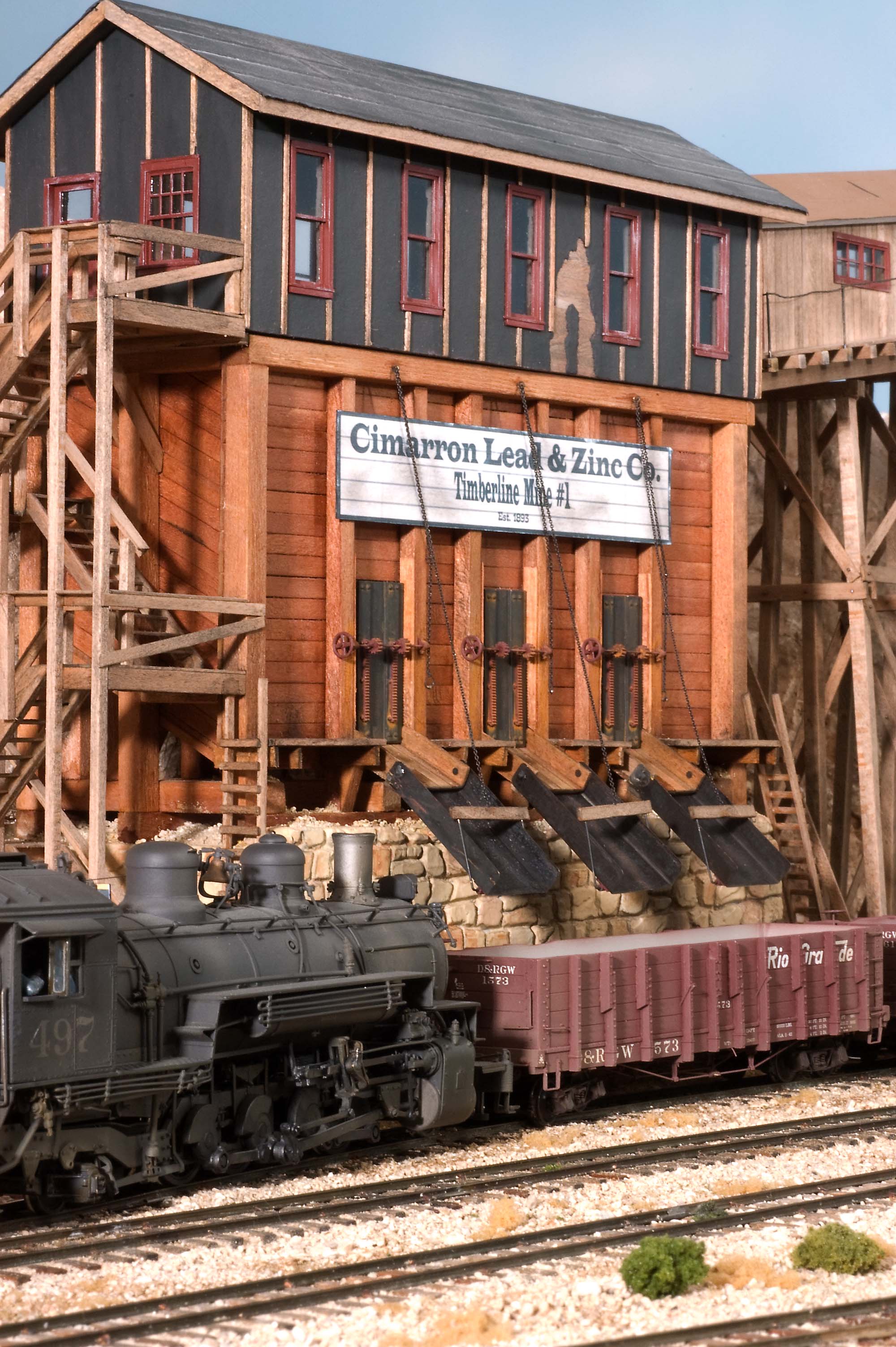 Photo 202 D&RGW #497 spots one of three cars in loading position at the bunker of the Cimarron Lead and Zinc Company's Timberline Mine #1. I hope you enjoyed this document. While the model is built to S scale, many of the techniques employed in its construction can also be used in many of the other scales. |
Click Here To Return To Railroad Home Page