

Welcome to my world of Sn3 Scale Model Railroading
Cimarron & Tall Timbers RR
"Building The Stock Pens"
By
Tom Troughton, MMR

 This document illustrates the steps I took to build a Banta Model Works, "Stock Loading Pens" kit. It's a laser cut wood kit comprised of intricately cut 1/32" plywood, various sizes of bass wood components, printed instructions and drawings and a CD of photos of the original chutes and pens that were designed by Jerry Wilson. The pens in this kit are similar to those that have been reconstructed by the U.S. Forest Service at Cimarron, Colorado.The size of my finished model is 14.75" from side to side and 12.25" from the back fence to the front edge of the loading platform. White glue, "Dr. Mike's" and "Lightning Bond" AC adhesives and "5-Minute Epoxy" were use to assemble this kit. I also used an X-acto knife, razor saw and PBL nippers to cut the parts and a dental pick to place the dots of glue and AC adhesive. All the wood was colored with a mixture of black shoe dye and rubbing alcohol before I started assembly. | |
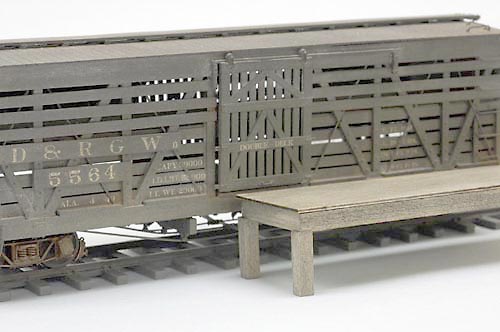 Photo 1. The first thing I had to do to match the height of the loading platform with the height of the car floor. This image shows the finished platform against a standard PBL stock car. | 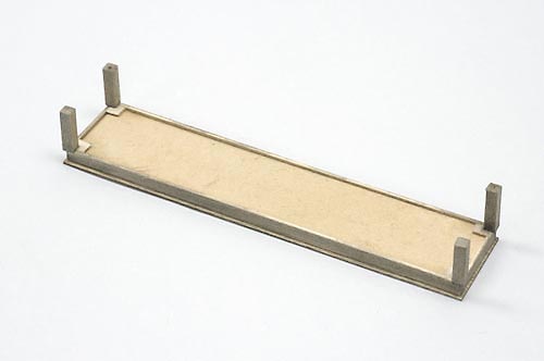 Photo 2. Rather than build up the underside of the platform with strip wood, I used a piece of 1/8" untempered Masonite and glued the appropriate laser cut and strip wood pieces to it. Small pieces of scrap material were glued under the legs to provide a flush surface to attach them to the platform. |
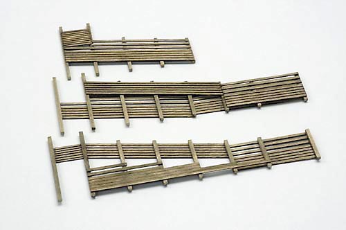 Photo 3. The three major components of the chute sides are illustrated here. They were assembled over the instruction drawings. | 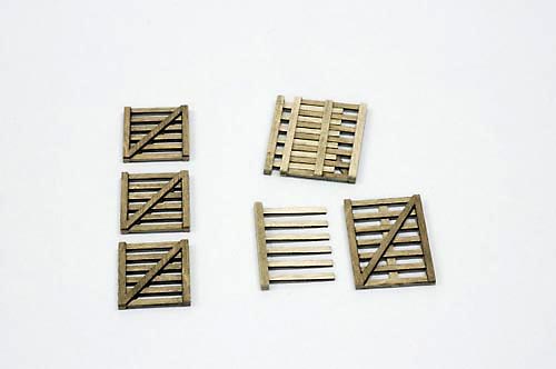 Photo 4. There are several gates to be built. Unfortunately, I didn't use any of the three small gates on the left side in my loading pens configuration. The components on the right make up the expansion gates that extend from the chutes to the side of the stock car. |
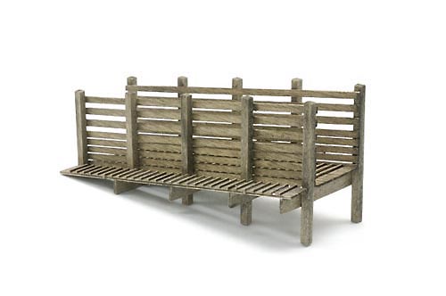 Photo 5. There's enough material in the kit to make a single chute, if you need it. I built this one before realizing that it wouldn't fit into my scheme. It will be used somewhere else on the layout. | 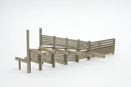 Photo 6. The "Z" brackets provide the supports for both the livestock and people walkway surfaces of the chute assemblies. |
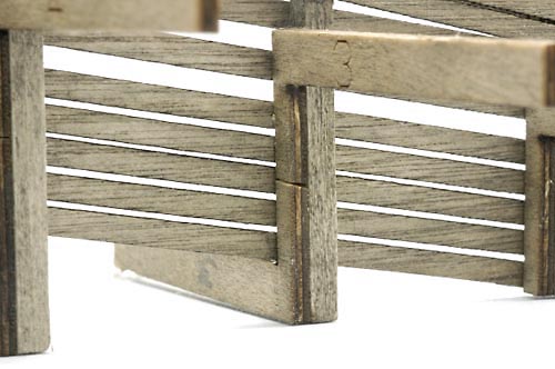 Photo 7. I had to make a height adjustment in a couple of the "Z" brackets. Merely cutting the vertical component and removing a small amount of material allowed the bracket to rest up against the lower board of the chute fencing. | 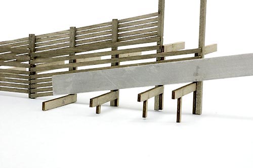 Photo 8. To verify that the "Z" brackets were properly attached, I used a metal straight edge to check their alignment. |
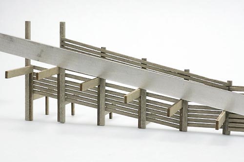 Photo 9. Both the upper and lower chute supporting surfaces were checked with the metal straight edge. | 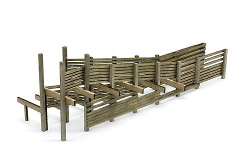 Photo 10. This view shows the upper chute fencing components attached to the "Z" brackets. |
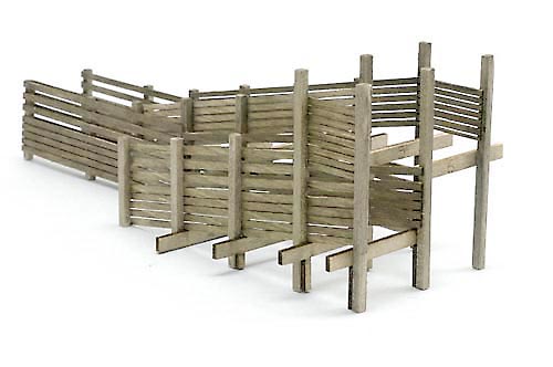 Photo 11. The lower chute fencing was added next. Please Note: When you are attaching the "Z" brackets, make sure their part number is facing away from the viewing side of the model, unlike in mine. I had to scratch, fill and sand mine to hide them. | 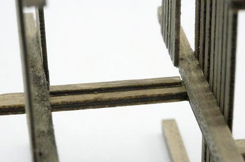 Photo 12. A small piece of the thin plywood was glued to the inner surface of the "Z" bracket to provide a gluing support for the livestock walkway. |
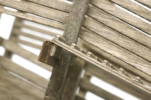 Photo 13. Another piece of scrap was also used to support the end of the upper end of the people walkway. | 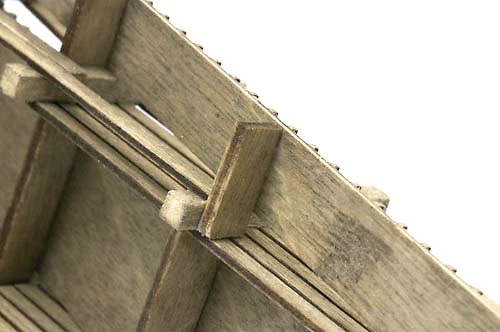 Photo 14. I also added another small piece of scrap wood to support the lower end of the people walkway. |
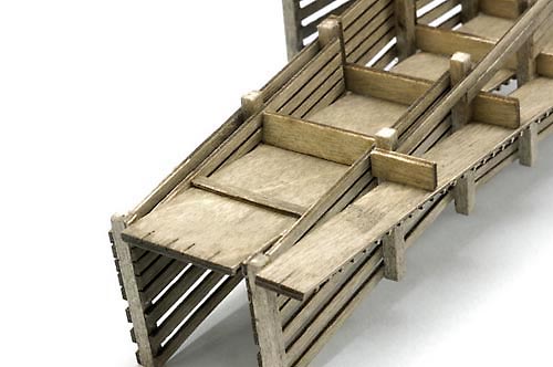 Photo 15. I also felt that the lower end of the stock walkway needed some additional support so another piece of scrap wood was added here too. | 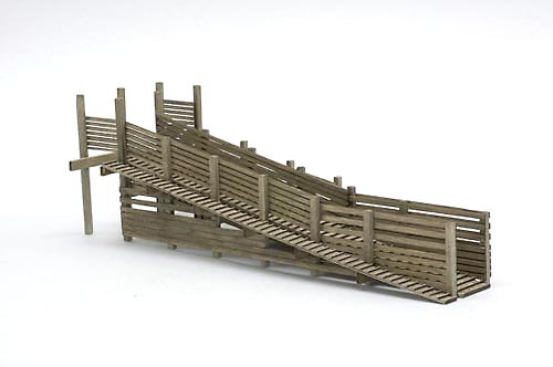 Photo 16. This view shows the upper chute with both walk ways installed. |
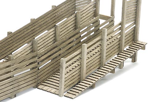 Photo 17. Here is the lower chute assembly with both walkways glued in place. | 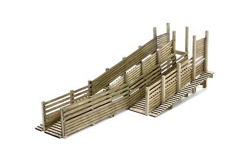 Photo 18. Here's a wider view of the chute assembly with both the upper and lower walkways secured in place. |
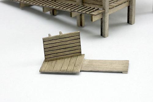 Photo 19. An interesting part of the loading chutes is this "drop gate and floor" piece. It swings up and out of the way when the lower chute is in use. | 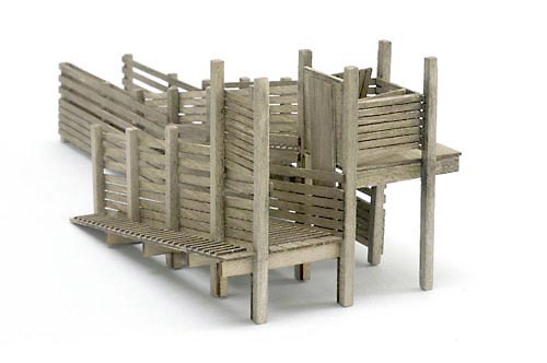 Photo 20. This view shows it in the "Up" position. |
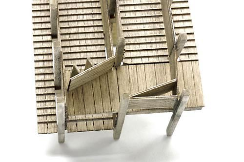 Photo 21. This overhead view shows the piece in the down position. | 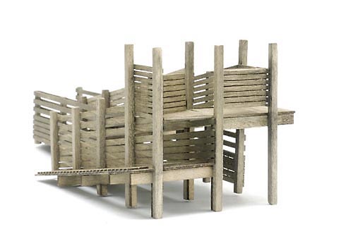 Photo 22. Here's a view of the"drop gate & floor" in the down position. Also notice that the numbers that were visible in the "Z" brackets have been filled, sanded and roughened up to remove them. |
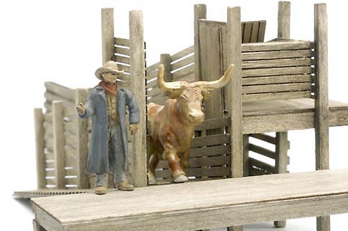 Photo 23. I placed a cowboy and a long horn steer on the chute assembly just to see how things looked at this point in the building process. | 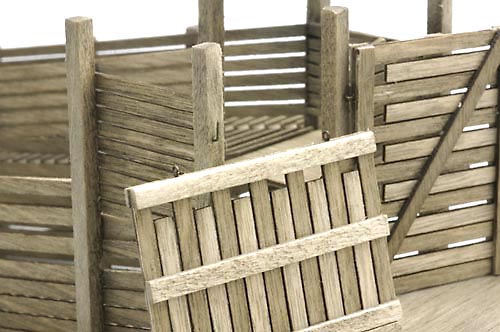 Photo 24. This view of the extension gates shows the tiny hook and eye details I used to make the hinges. Some of the eyes are HO scale from Detail Associates, but when I ran out of them, I bent my own from small wire. |
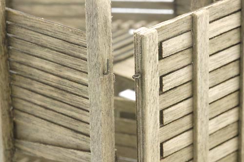 Photo 25. The eyes of the gates are simply set in place on the "L" shaped hook. Both the hook and eye pieces were attached with Dr. Mikes "Lightning Bond" AC adhesive. | 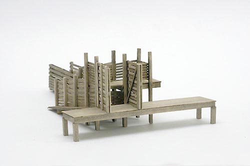 Photo 26. This view shows the expansion gates in the position they would be in when loading stock. |
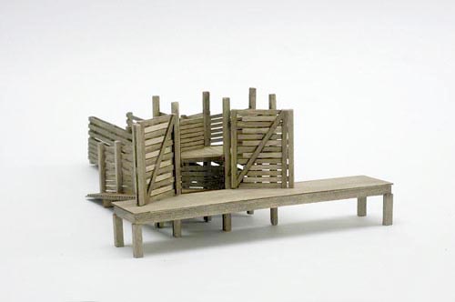 Photo 27. When they are not in use, they can be swung back away from the tracks to await the next shipment of livestock. | 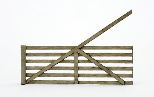 Photo 28. The large gates were constructed next. Once I decided which side of the gate would have the posts and laser cut pieces, I attached a piece of the 6" x 6" fencing post material to one end of the fencing piece. The vertical piece of the laser cut diagonal component was centered directly over the uncut frets on the fencing and butted up against the short end post. |
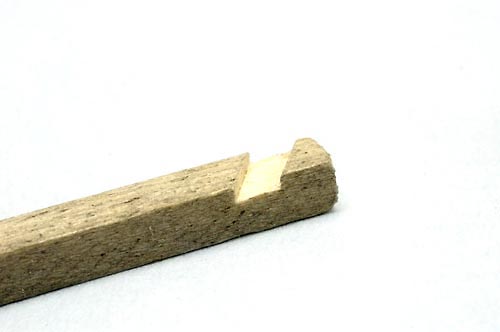 Photo 29. I positioned the 8" x 8" post in position and marked where the diagonal brace would be fastened. A small dado was cut with the X-acto knife. | 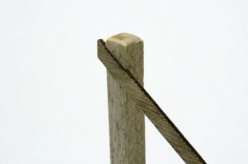 Photo 30. The fresh cut wood was stained with the show dye & alcohol solution. When it dried, it was glued to the post. |
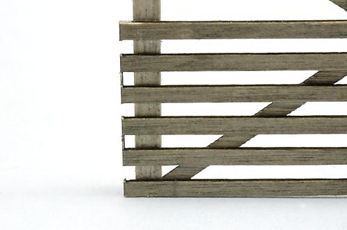 Photo 31. The fencing was glued to the 8" x 8" post at the same time. When the bonds were dry, the excess was nipped off and sanded smooth. | 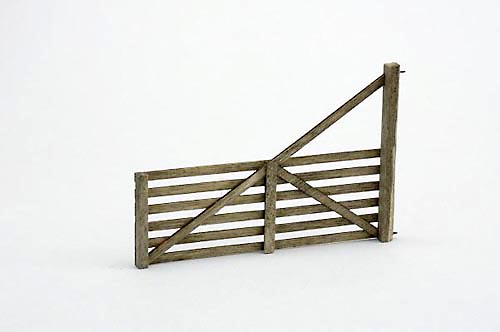 Photo 32. This view shows the finished gate with the eye bolts inserted and glued in place. I had to remove some of the edges of the 8" x 8" post to allow it to swing open wider. |
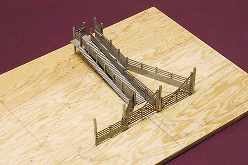 Photo 33. I treated the movement of stock through the pens as one would when working themselves through a maze puzzle. Because of my final "traffic pattern" I didn't use the small gates that I built up earlier. Instead, I extended the chute fencing from the lower gate and created an "angled entrance" to it. | 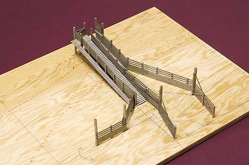 Photo 34. This view shows the movable gates in their opened position. The chute assembly was attached to the plywood support board with dots "5-Minute epoxy". The glue joints for the large swinging gate posts were strengthen with metal pins and as well as the epoxy. |
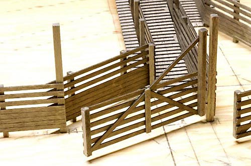 Photo 35 This view shows the partially opened gate leading to the upper chute. | 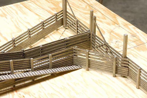 Photo 36. This is a "front" view of the gates leading to the chutes. |
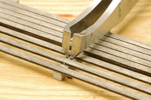 Photo 37. A pair of PBL nippers was used to remove the frets that were not cut by the laser. These thin pieces of wood help hold the fencing together while it is being assembled. The cuts were dressed up with a wire brush and sanding sticks. | 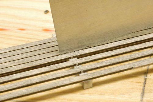 Photo 38 A thin blade razor saw was used to remove the uncut frets from the thinner areas of the fencing material. I also used a wire brush to clean up these cuts. |
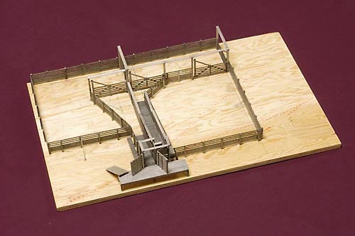 Photo 39. This overhead view shows the completed loading pen assembly with all the gates closed. | 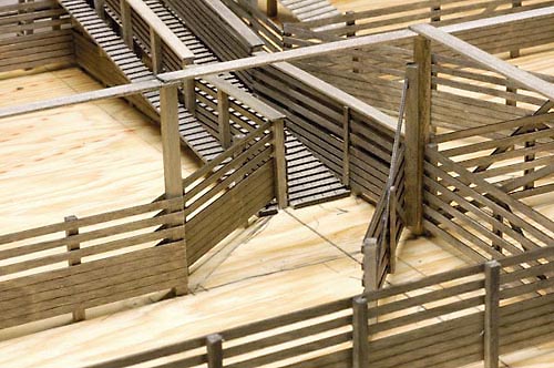 Photo 40. Here's a view showing the entrance throat to the upper chute. The 2" x" 12" planks have been attached to the tops of the large gate posts. These planks help maintain alignment of the posts and add to their stability. |
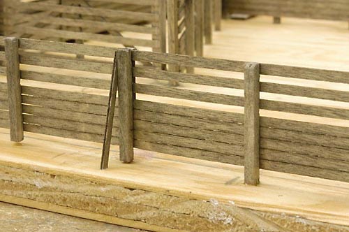 Photo 41. I added fence post braces in a few locations to suggest reinforce that had to be added to stabilize them. This view also illustrates the "bottom" side of the laser cut fencing by showing how thin the lines or gaps are between the lower boards. The fencing was assembled so that this surface was positioned so it wouldn't be easily seen by viewers. | 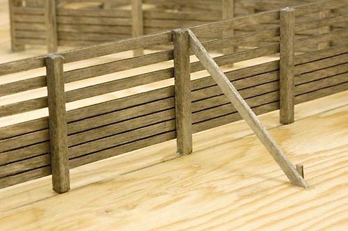 Photo 42. This view shows the "top" side of the laser cut fencing. Note how more pronounced the gaps between the lower boards appear in this photo than they do in the previous one. |
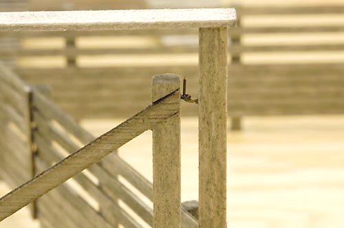 Photo 43. Here's a close up view of one of the swing gate "hook and eye" hinges. | 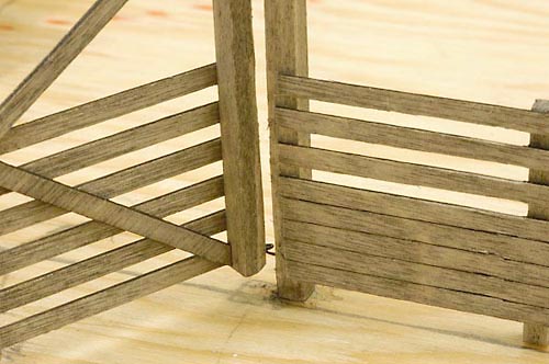 Photo 44. The cuts in one of the gate posts where I removed some material are visible here. By "rounding out" the posts a bit, the gates can be opened wider. |
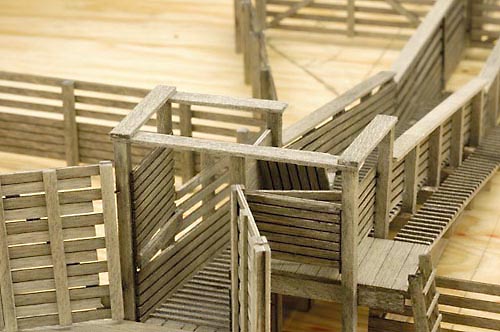 Photo 45. Planking has been added to the tall supporting posts of the loading chute as well as along the chute fencing. | 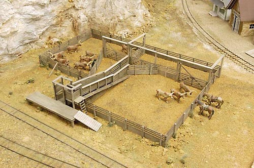 Photo 46 Here's an overhead view of the completed pens. The ground cover is dirt from Cimarron, Colorado and my garden. |
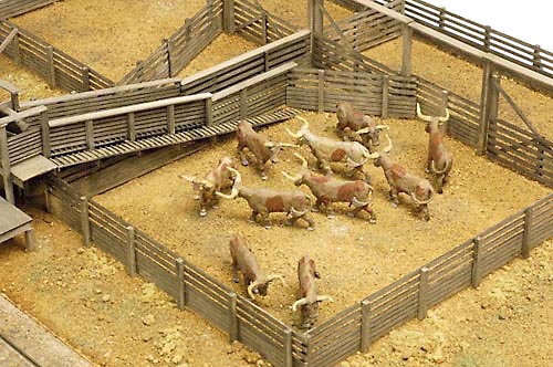 Photo 47. The long horn steers are from "Fun & Games". | 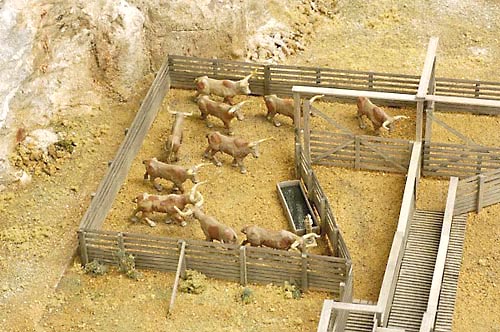 Photo 48. I made a stock watering tank out of plywood scraps. The water is a piece of untempered Masonite that I painted "Grimy Black" and coated with Future Floor Wax. |
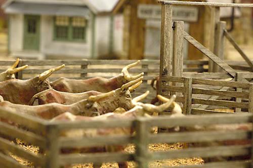 Photo 49. This shot shows how close the pens are from some of the buildings of my town of Tall Timbers, CO. | 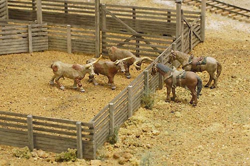 Photo 50. The horses are from "The Aspen Modeling Company". |
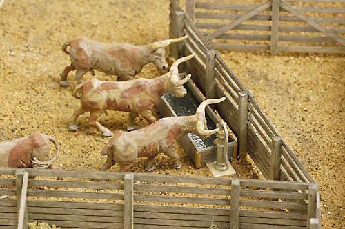 Photo 51 The metal hand pump is a detail part from Banta Model Works. I glued it to a styrene base and painted it with Polly Scale "Flat Aluminum". | 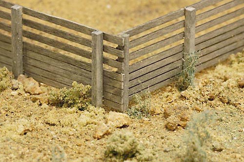 Photo 52. Ground foam from Woodland Scenics has been added along with bushes made from Scotch-Gard cleaning pads. |
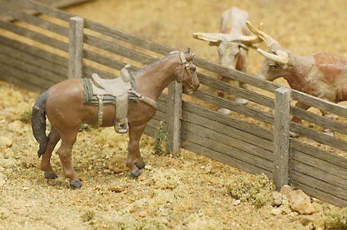 Photo 53. Here's another view of the steers and one of the horses. | 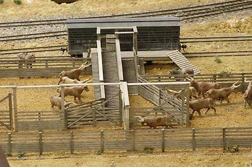 Photo 54. This view is from the back side of the pens towards the track. A stock car has been spotted at the chutes for loading. |